EasyManuals Logo

Mindray A9 Service Manual

Mindray A9
424 pages
To Next Page IconTo Next Page
To Previous Page IconTo Previous Page
Page #88 background imageLoading...
Page #88 background image
2-60
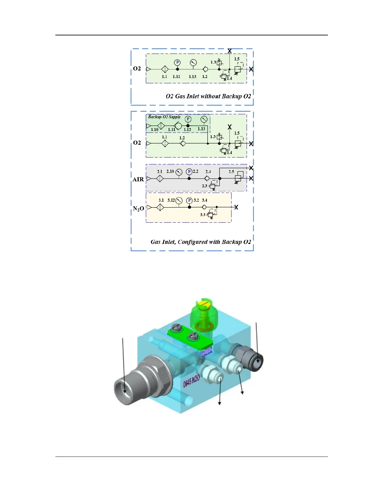
Figure 2 Pneumatic diagram of the gas inlet assembly
As shown in the above figure, the gas inlet assembly consists one or more of the following
components based on different configurations: gas hose connector, filters (1.1, 1.10, 2.1, and 3.1),
check valves (1.2, 1.11, 2.4, and 2.9), pressure relief valves (1.4, 2.3, and 3.3), regulators (1.5 and
2.5), pressures switch (1.3), and pressure sensors (1.12, 2.10, and 3.2). Structural diagrams of the
gas inlet assemblies are shown below.
Figure 3 Structural diagram of the N2O inlet assembly
N2O inlet
N2O cylinder inlet
Pressure test connector
Outlet

Table of Contents

Other manuals for Mindray A9

Questions and Answers:

Question and Answer IconNeed help?

Do you have a question about the Mindray A9 and is the answer not in the manual?

Mindray A9 Specifications

General IconGeneral
TypeAnesthesia Workstation
Integrated Gas AnalysisYes
Backup BatteryYes
Operating Temperature10°C to 40°C
Storage Temperature-20°C to 55°C
Battery TypeLithium-ion
Ventilation ModesVolume Control, Pressure Control, SIMV, Manual Ventilation
DisplayTouchscreen
Patient MonitoringECG, SpO2, NIBP, EtCO2, Temperature
ConnectivityEthernet, USB
PortabilityMobile (with wheels)
Battery LifeMinimum 90 minutes (typical)
AltitudeUp to 3000 meters
Power Supply100-240 VAC, 50/60 Hz
Charging TimeApproximately 4 hours
StorageInternal storage for patient data and system logs
Supported LanguagesMultiple languages
CertificationsCE, FDA

Related product manuals