EasyManuals Logo

Mindray A9 Service Manual

Mindray A9
424 pages
To Next Page IconTo Next Page
To Previous Page IconTo Previous Page
Page #91 background imageLoading...
Page #91 background image
2-63
Figure 7 Structural diagram of the cylinder yoke assembly
2.3.2.3 ACGO Assembly
The ACGO assembly outputs the gas flowing through the vaporizer manifold and the flushed O2
to the breathing circuit or directly to the independent ACGO outlet. The ACGO assembly also
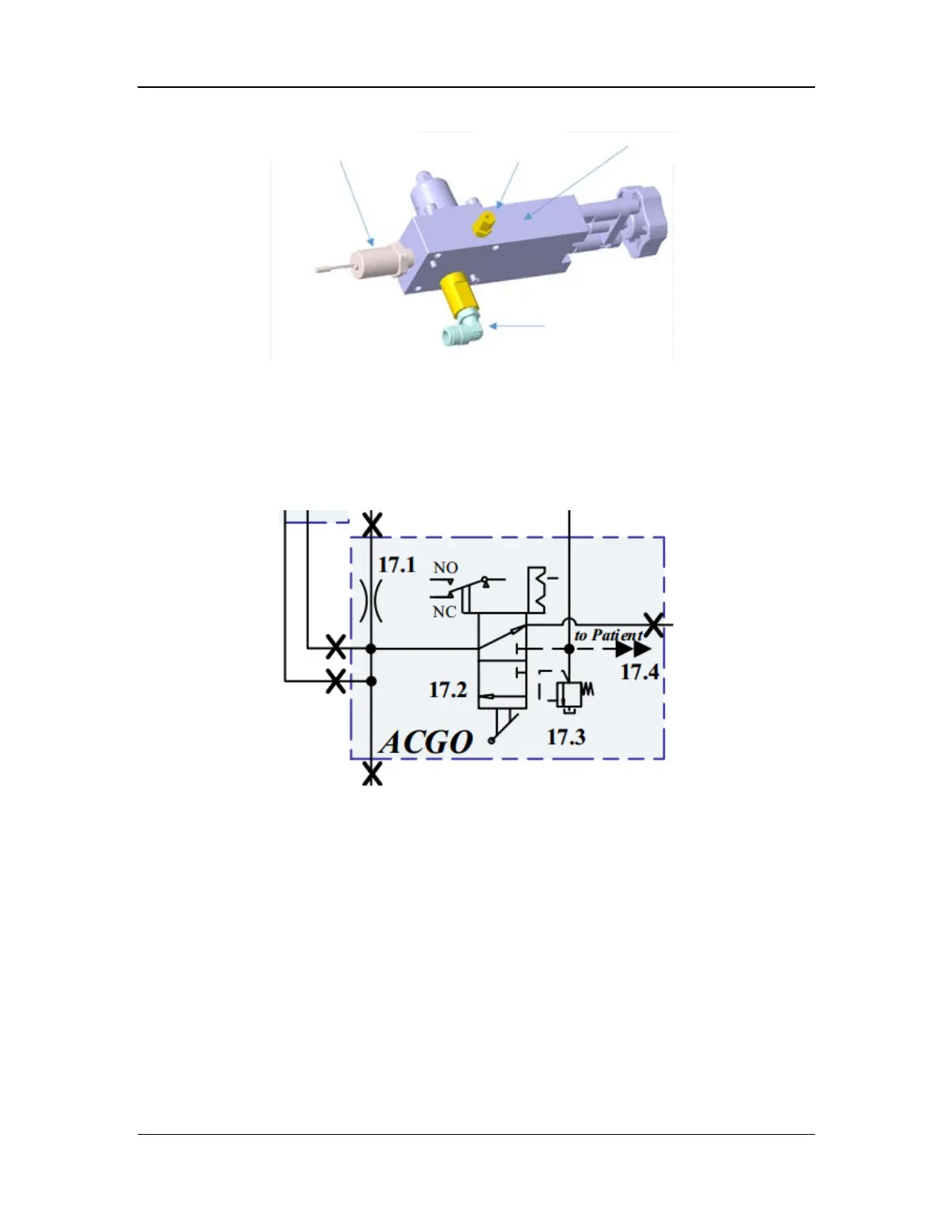
provides an AG module sampling connector. The pneumatic diagram of the ACGO assembly is
shown below.
Figure 8 Pneumatic diagram of the ACGO assembly
The ACGO assembly consists of the knob, 11 kPa (112 cmH
2
O) pressure relief valve (17.3),
microswitch (17.2), AG module sampling connector, O2 flush inlet, fresh gas inlet, and common
gas outlet. The structural diagram of the ACGO assembly is shown below.
Electronic pressure sensor
Copper tube
connector
Pressure reducer
Check valve

Table of Contents

Other manuals for Mindray A9

Questions and Answers:

Question and Answer IconNeed help?

Do you have a question about the Mindray A9 and is the answer not in the manual?

Mindray A9 Specifications

General IconGeneral
TypeAnesthesia Workstation
Integrated Gas AnalysisYes
Backup BatteryYes
Operating Temperature10°C to 40°C
Storage Temperature-20°C to 55°C
Battery TypeLithium-ion
Ventilation ModesVolume Control, Pressure Control, SIMV, Manual Ventilation
DisplayTouchscreen
Patient MonitoringECG, SpO2, NIBP, EtCO2, Temperature
ConnectivityEthernet, USB
PortabilityMobile (with wheels)
Battery LifeMinimum 90 minutes (typical)
AltitudeUp to 3000 meters
Power Supply100-240 VAC, 50/60 Hz
Charging TimeApproximately 4 hours
StorageInternal storage for patient data and system logs
Supported LanguagesMultiple languages
CertificationsCE, FDA

Related product manuals