2-65
2.3.2.5 System Switch Assembly
The system switch assembly controls fresh gas supply of the breathing system. In addition, it
provides electrical signals of the system switch to realize synchronous on/off control on the
pneumatic system and the circuit system of the anesthesia machine. The system switch outputs
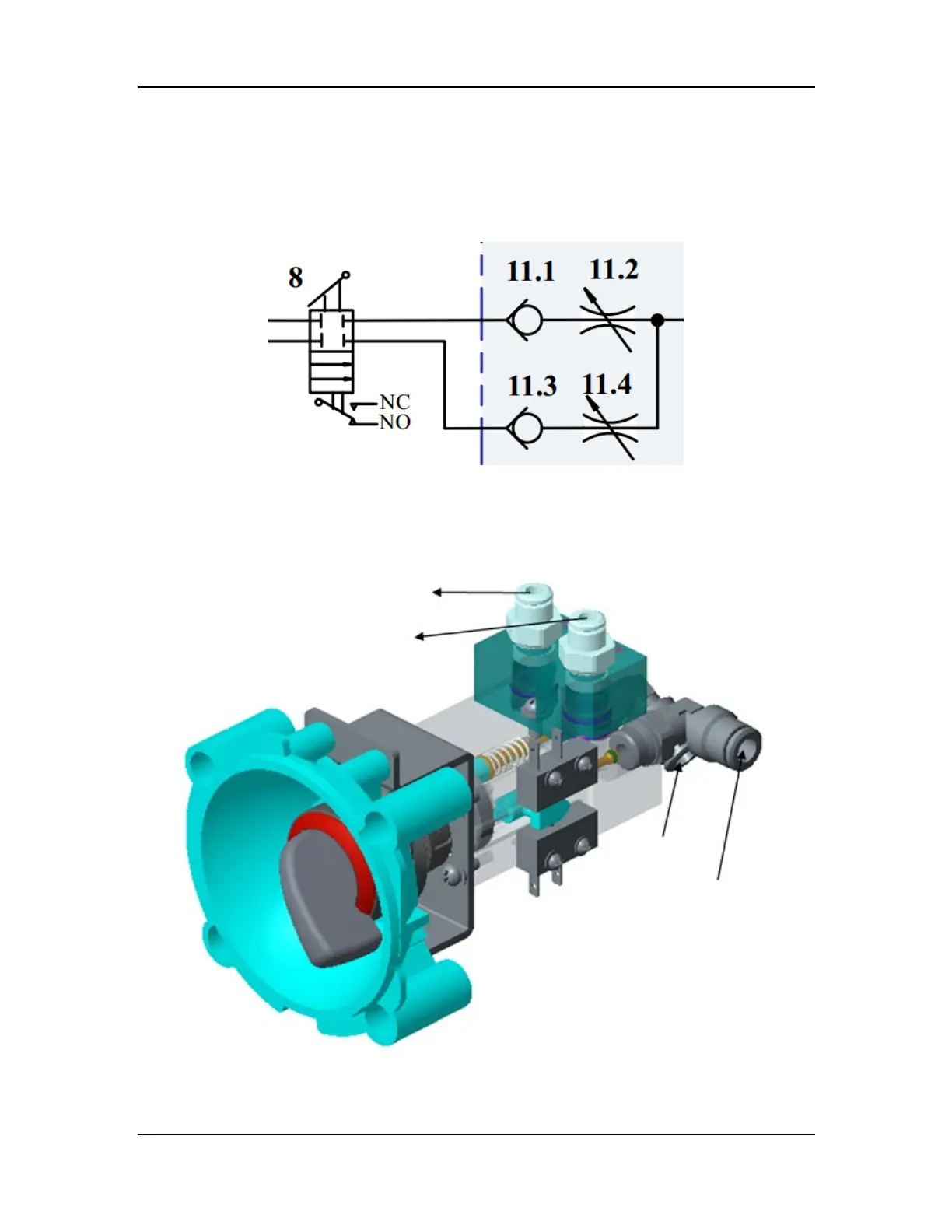
gas for the BFCS. The pneumatic diagram of the system switch assembly is shown below.
Figure 11 Pneumatic diagram of the system switch assembly
The system switch assembly controls O2 and air supply. Both branches are controlled by a
purchased switch knob. During switching, the two limit switches disposed symmetrically also
switch on or off at the same time, realizing on-off control based on electrical signals of the
system. Two check valves (11.1 and 11.3) are integrated at the system switch outlet to prevent air
and O2 inversion. The structural diagram of the system switch assembly is shown below.
Figure 12 Structural diagram of the system switch assembly