2-68
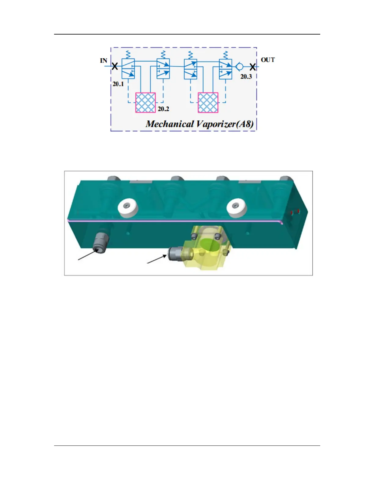
Figure 18 Pneumatic diagram of the mechanical vaporizer manifold assembly
The mechanical vaporizer manifold assembly consists of the check valve assembly, connector
assembly, locking plate assembly, vaporizer manifold, vaporizer pad, and inlet/outlet quick
connectors. The structural diagram of the mechanical vaporizer manifold assembly is shown
below.
Figure 19 Structural diagram of the mechanical vaporizer manifold assembly
2.3.4.2 Electronic Vaporizer (for A9)
The electronic vaporizer can accurately feed the anesthetic agent into the anesthesia breathing
circuit at certain concentration. During operating of the electronic vaporizer, the electronic
vaporizer manifold provides 150 kPa (22 psi) drive gas, which flows through the drive gas inlet
(14.3), mechanical pressure relief valve (14.6), pressure sensor (14.7), and drug pool entrance
switch valve (14.8) into the drug pool of the vaporizer. The drive gas drives the anesthetic liquid
in the drug pool to flow through the filter (14.11) and exit safety valve (14.12) into the injector
(14.13), which injects pure anesthetic liquid to the mixing chamber (14.16) at certain frequency.
In addition, the fresh gas of the anesthesia machine enters the mixing chamber through the fresh
air inlet (14.15), and is fully mixed with the anesthetic gas. Then the mixed gas is delivered to the
patient side through the fresh gas outlet (14.17). The pneumatic diagram of the electronic
vaporizer is shown below.