5 Fluid System 5-
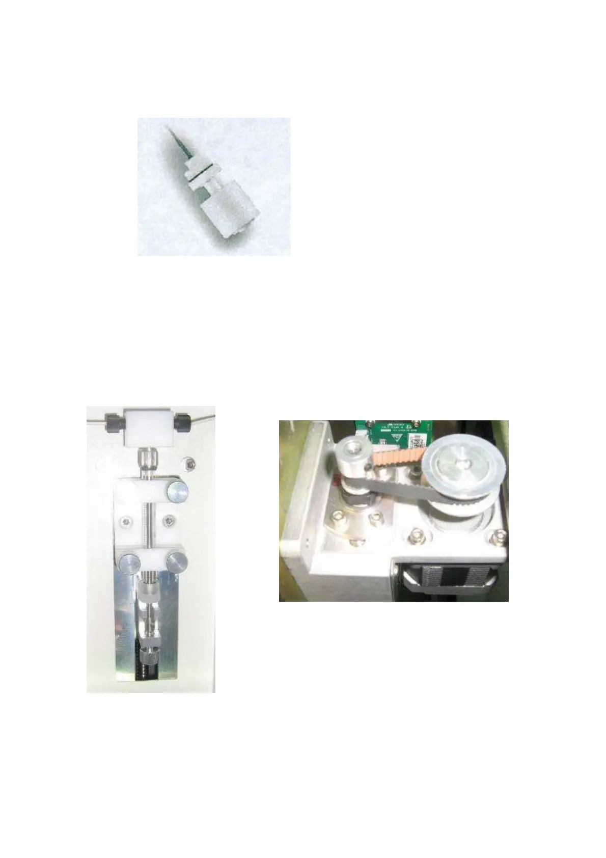
5.9.3 Liquid Level Float
Figure 5-9 Liquid Level Float Sensor
Applied Assemblies: DI water tank and waste tank
Function: The float sensor contains a spring switch and a circular magnet inside the sealed
plastic tubing. The spring switch is activated by the up-down movements of the float via the
magnet and then the liquid level is detected by the system.
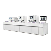
5.9.4 Syringe Assembly
Figure 5-10 Syringe Module
Applied assembly: sampling system.
Function: A step-motor drives the controlled spin of the screw-rod that leads to the up-down
movements of the syringe in a quantitive manner. Therefore, the accurate sampling of the
reagent/sample is achieved in this way.