3 Installation 3-
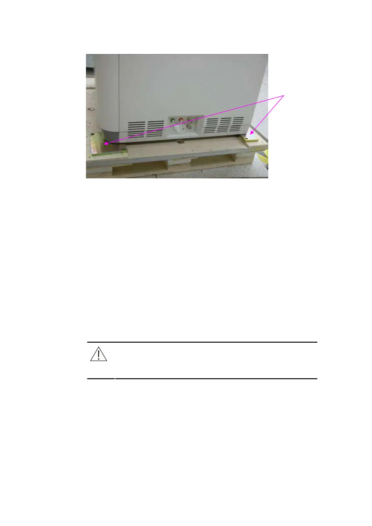
Figure 3-4 Remove the Fixing Plate
3.3.2 Installation
Fix the analyzer: after the analyzer is placed on the target installation site,
adjust the two front fixing bolts to ensure the four of them have the same
height (the two behind are not adjustable).
Remove the plastic cover and fixing bandage, and install the sample probe
and mixing bar. Do not install the arm cover of the sample probe before
calibrating the level detection board.
• Place the ANALYZING UNIT POWER to ON while ensuring that the sample
probe is not attaching any conducting .object, such as hands.
• Calibrate the sample probe manually. Check if indicator D2 (yellow) is
lightened within 2 seconds when the ANALYZING UNIT POWER to ON. Press
the switch S2 on the level detection board and then release it, then check if
indicator D2 is first extinguished and then lightened. If it is, that means the
calibration succeeds.
Exercise caution to prevent the sample probe from attaching any conducting
object during the calibration.
• Place the ANALYZING UNIT POWER to OFF.
NOTE:
::
:
Remember to install the washer when installing the sample probe.
Use syringe to inject water into the filter and connect the filter to the cap assembly of
the DI water tank. Connect the liquid tubes as indicated in the following figure.
Remove the
package
plates of the
front and back
feet.