4 Units Description
4-32
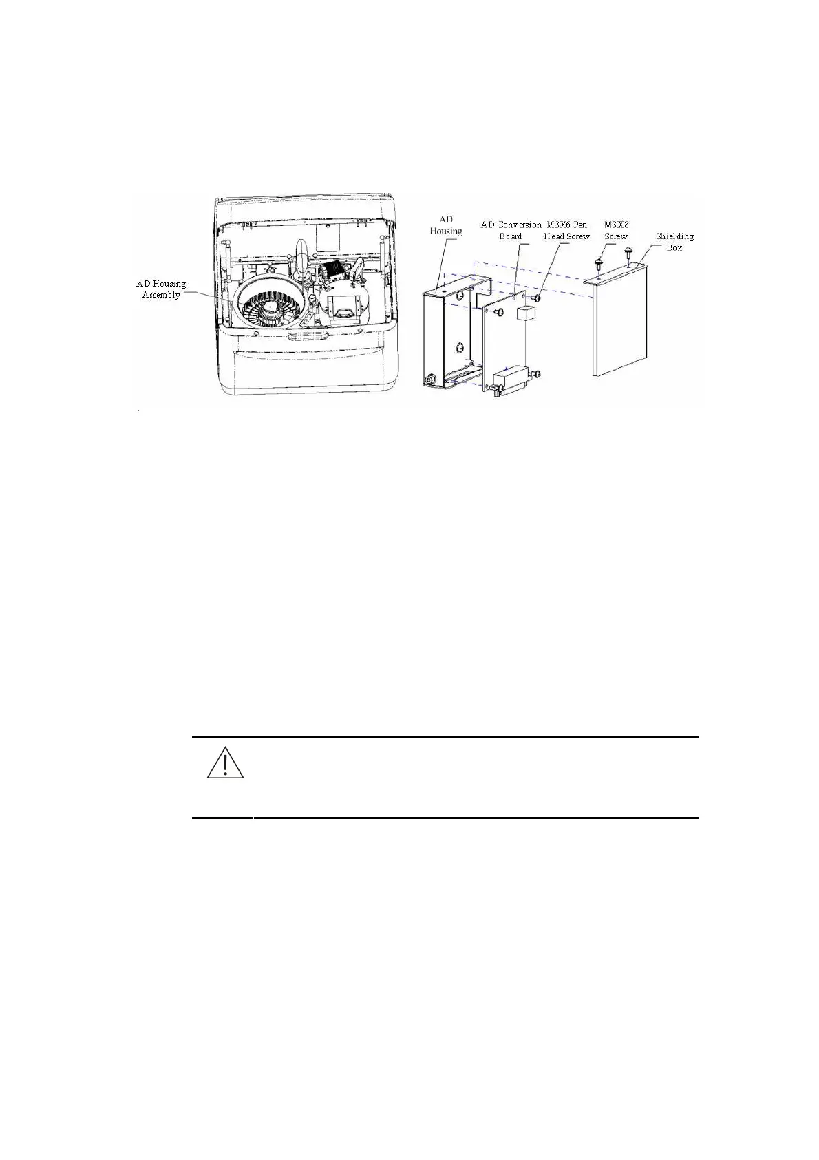
4.6.3.3 AD Housing Assembly
Figure 4-37 AD Housing Assembly
1. Remove the three table panels to expose the AD housing assembly.
2. Unscrew the two M3X8 screws allocated with pad and remove the shielding box.
And then repair the AD conversion board.
3. Unscrew the four M3X6 pan head screws and then replace the AD conversion
board.
4.6.4 Adjustment of Photometer
4.6.4.1 Adjusting Photometric Position of Reaction Disk
The photoelectric collecting position in the reaction disk depends on the installing
position of the coder sensor of the reaction disk. Any slight movement of the sensor will
change the photoelectric collecting position and then affect the performance of
photoelectric collection. Therefore, don’t remove the coder sensor unless it is
necessary.
CAUTION
Don’t remove the coder sensor of the reaction disk unless it is
necessary.
It is necessary to check the photoelectric collecting position after replacing the the
coder sensor or tightening the screw of the sensor bracket,
The adjustment of photometric position is carried out by using an oscillograph to
measure the photoelectric analog signal and the AD collection start signal. The probe
of the oscillograph should be connected to the specified signal test point.
The adjusting steps are described as follows.
1. Make sure to turn off the power switch of the analyzing unit.
2. Open three table panels to expose the AD housing assembly. (See Figure 4-37)