4 Units Description
4-
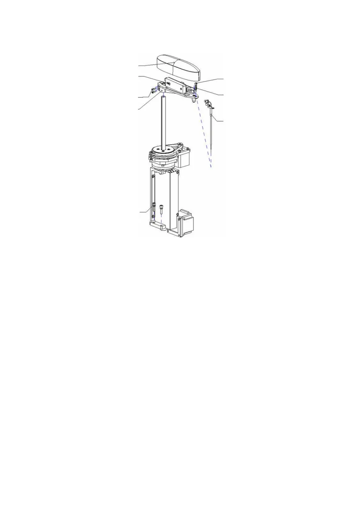
Figure 4-7 Dismounting of Sample Probe Unit
Arm Cover
M3X10 Screw
Guiding pole
Probe Arm
Assembly
Arm Base
Obstruction
Spring
The Probe
Assembly
M5X20 Screw
Dismounting steps are shown as follows.
a. The probe assembly is fixed to the probe arm assembly by the guiding pole and
obstruction spring. Remove the probe assembly by removing the arm cover, guiding
pole and obstruction spring.
b. The probe arm assembly is fixed to the probe drive assembly with two M3X10
hexagon socket head screws allocated with spring pad. Remove the probe arm
assembly by loosening the two socket screws.
c. The sample probe unit is fixed to base board via three M5X20 hexagon socket head
screws allocated with spring pad. Remove the sample probe unit by loosening the
three socket screws.
Reverse the steps described above to mount the sample probe unit.
Precautions:
1. After installing the probe into guiding pole with obstruction spring, make sure probe
assembly move freely up and down. If not, you should adjust the guiding pole to make it
move freely. Otherwise the function of protecting the probe against collision in the
vertical direction may not work well.
2. Make sure that the probe surface is clean while removing and installing the probe
assembly.
3. Disconnecting correlative power cables, data cables and liquid connecting before
performing the above steps.
 Loading...