4 Units Description
4-
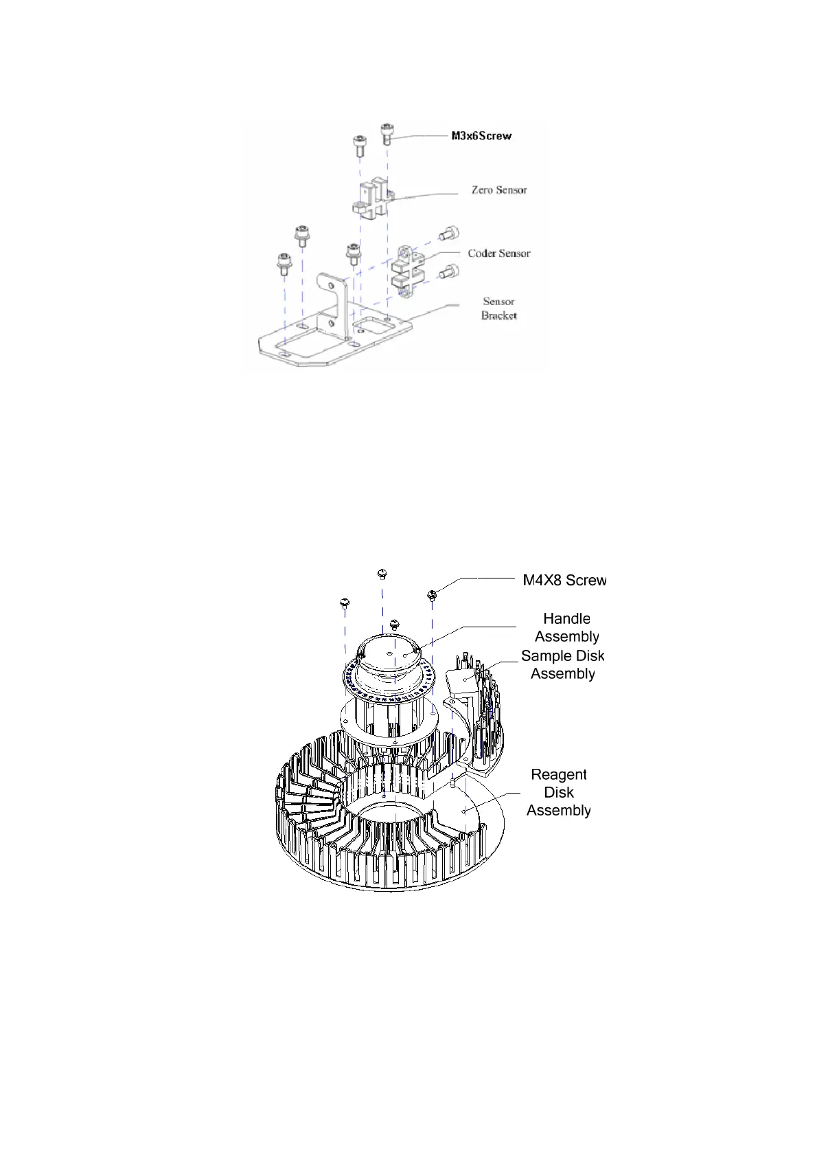
Figure4-16 Sensor Assembly
Remove two M3x6 hexagon socket head screws, and then remove the zero sensor and
coder sensor which are fixed to the sensor bracket.
Precautions:
The positions of zero sensor and coder sensor can not be changed.
4.3.3.3 Disk Assembly
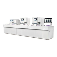
Figure4-17 Sample/Reagent Disk Assembly
Remove the handle assembly which is fixed to reagent disk assembly by loosening four
M4x8 cross pan head screws. The sample disk assembly can be taken out from the
reagent disk assembly directly. The introduction of reagent disk assembly and sample
disk assembly is as follows.