4 Units Description
4-
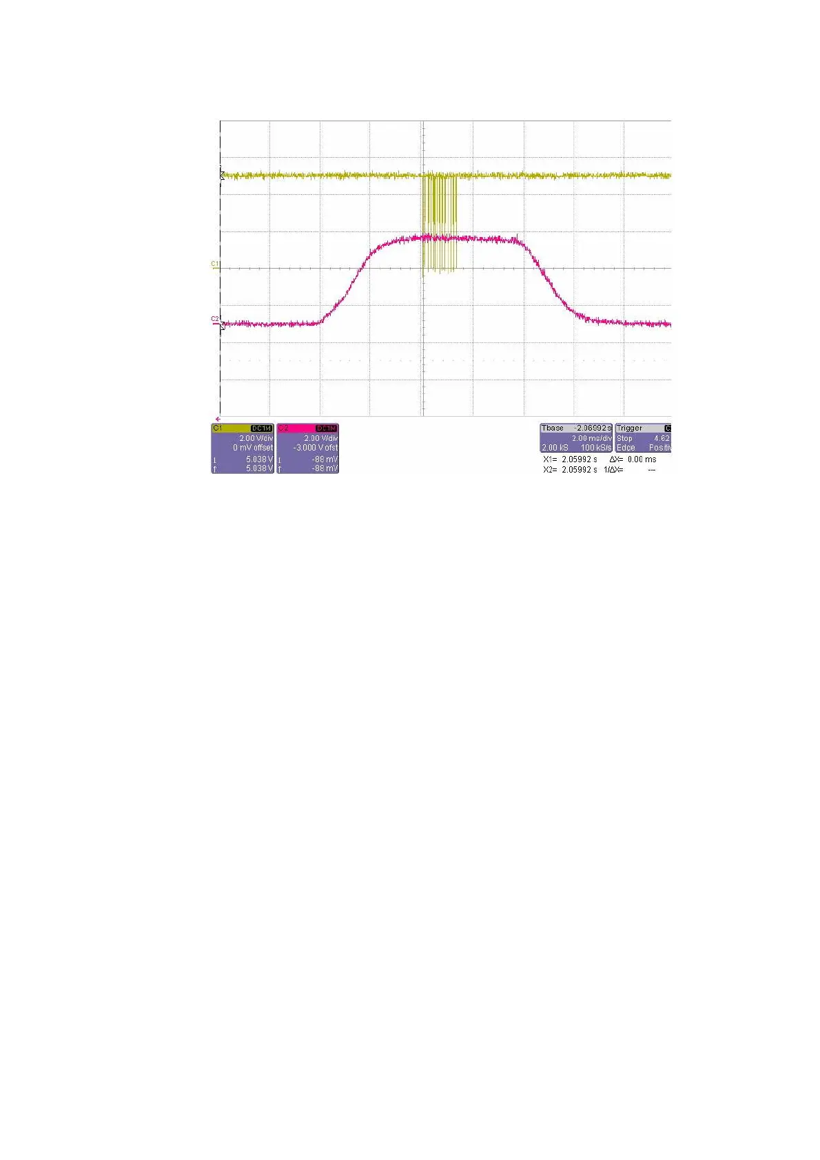
Figure 4-41 Photometric Wave Feature
8. If the AD start signal is in the decreasing part of the photomectric analog signal
instead of the middle part, the photomectric position is not proper and must be
adjusted by moving the coder sensor of the reaction disk. If the AD start signal is
on the left, then move the sensor along clockwise. If it is on the right, move the
sensor along counter-clockwise. The left panels, right panels and front panels
should be removed for adjusting the sensor.
10.
Adjust the coder sensor of the reaction disk: the sensor is fixed on the sensor
bracket and only the sensor bracket should be adjusted.See Figure 4-42, loosen
the three screws and adjust the sensor bracket position according to the
photoelectric wave. After completing the photomectric position adjustment, tighten
the three screws.
11.
After finishing the above operation, send Ordinary Rotate&Measure Instruction
and check the photometric waves again.