4
SETUP AND PROCEDURES BEFORE OPERATION
4.4 Wiring
4.4.2 External wiring
4 - 9
1
OVERVIEW
2
SYSTEM
CONFIGURATION
3
SPECIFICATIONS
4
SETUP AND
PROCEDURES
BEFORE OPERATION
5
UTILITY PACKAGE
(GX CONFIGURATOR-
AD)
6
PROGRAMMING
7
ONLINE MODULE
CHANGE
8
TROUBLESHOOTING
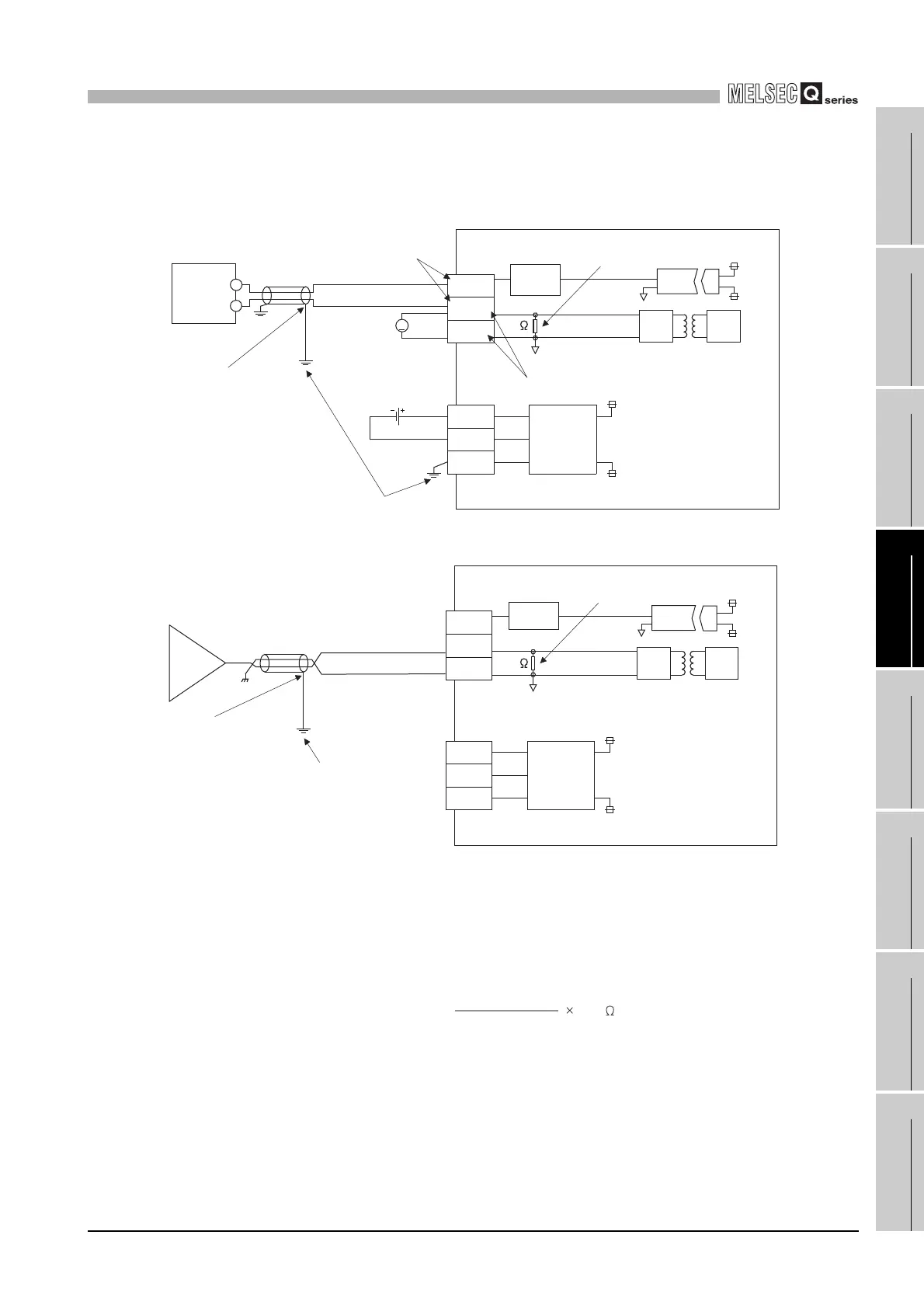
(2) Q66AD-DG
(a) For 2-wire transmitter input
(b) For current input
*1 Use a 2-core twisted shielded wire for the power wire.
*2 Shows input resistance.
*3 To connect with the 2-wire transmitter, be sure to connect to P and I+/CHK+.
*4 Always ground the shield of the wire of each channel.
*5 The check terminals (CHK+, CHK-) are used to check the amount of input in mA in relation to the
2-wire transmitter output.
This can be checked since analog inputs of 4 to 20mA are converted to analog outputs of 1 to 5V.
The relationship of this conversion can be expressed by the following formula:
*6 When all the channels used are for current input, wiring for 24VDC is not required.
Note that to use the Q66AD-DG with a product number (first five digits) of 15031 or earlier, refer
to Appendix 2.
2-wire
transmitter
(4 to 20 mA)
*1 Shielded
V
+
+
-
V-
V
P
I+/CHK+
I-/CHK-
Filter
24V
24G
24V
24G
Current
limiting
circuit
Transmitter
power
supply
24VDC
*4
*5
*2
*3
24V
24G
FG
Demodu-
lator
Modu-
lator
250
*1 Shielded
P
I+/CHK+
24V
24V
24G
24G
*4
*2
I-/CHK-
Current
limiting
circuit
Transmitter
power
supply
Modu-
lator
Demodu-
lator
*6
250
Filter
24V
24G
FG
GND
nalog output(V) =
Analog input(mA)
1000
250
 Loading...


