3 - 35
3.3 I/O Signals for the Programmable Controller CPU
3.3.2 Details of I/O signals
3
SPECIFICATIONS
3.3.2 Details of I/O signals
I/O signals for the A/D converter modules are explained in detail below.
(1) Input signals
*1 A watchdog timer error occurs when the program calculations are not completed within the
scheduled time due to malfunctions of A/D converter module hardware.
When a watchdog timer error occurs, the RUN LED for the A/D converter module turns off.
Device No. Signal Name Description
X0 Module ready
(1) When the programmable controller CPU is powered on or reset, this signal turns on once the
preparation for A/D conversion has been completed, and A/D conversion processing is then per-
formed.
(2) In either of the following states, the Module ready (X0) turns OFF.
During offset/gain setting mode (A/D conversion processing is performed.)
When the A/D converter module has a watchdog timer error
*1
(A/D conversion processing is not performed.)
X7
High resolution
mode status flag
(1) This turns ON when in high resolution mode.
X8
Warning output
signal
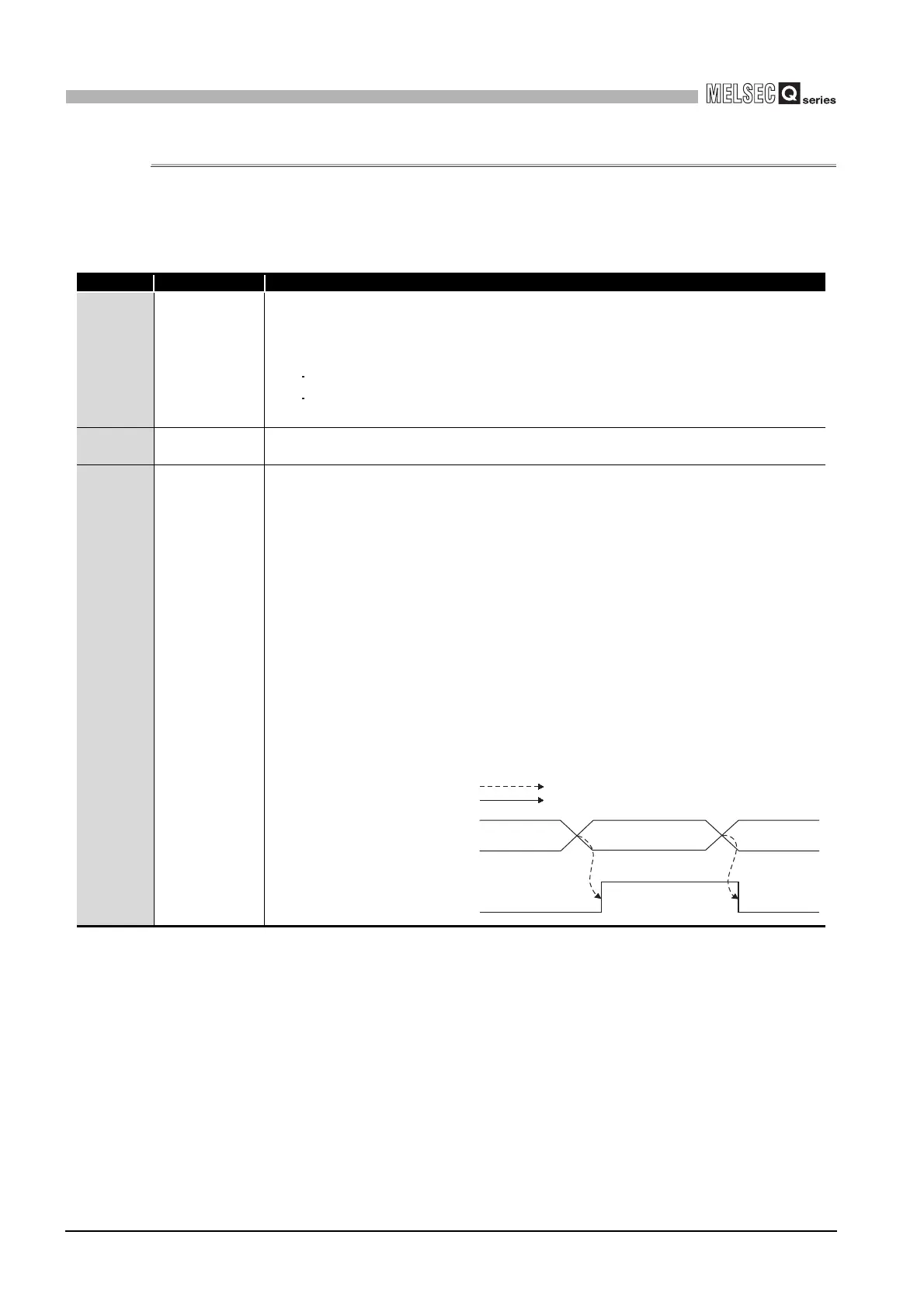
(1) The Warning output signal (X8) turns ON at detection of a process alarm or rate alarm.
(a) Process alarm
1) This signal turns ON when the digital output value falls outside the setting range set to
the process alarm upper/lower limit values (Un\G86 to Un\G117) on any of the
channels enabled for A/D conversion after the process alarm function has been made
valid.
2) As soon as the digital output values return to within the setting ranges on all channels
enabled for A/D conversion, this signal turns OFF automatically and the ALM LED is
also extinguished.
(b) Rate alarm
1) This signal turns ON when the varying rate of the digital output value falls outside the
varying rate range set to the rate alarm upper/lower limit values (Un\G122 to Un\G137)
on any of the channels enabled for A/D conversion after the rate alarm function has
been made valid.
2) As soon as the varying rates of the digital output values return to within the preset
varying ranges on all channels enabled for A/D conversion, this signal turns OFF
automatically and the ALM LED is also extinguished.
Warning output flag
(Un\G50, Un\G51)
Warning output signal (X8)
Warning occurrence
(Process alarm, rate alarm)
00
Performed by the A/D converter module
Performed by the sequence program
 Loading...


