4 - 12
4.5 Intelligent Function Module Switch Setting
4
SETUP AND PROCEDURES BEFORE OPERATION
4.5 Intelligent Function Module Switch Setting
The intelligent function module switches are set using the I/O assignment settings of GX
Developer.
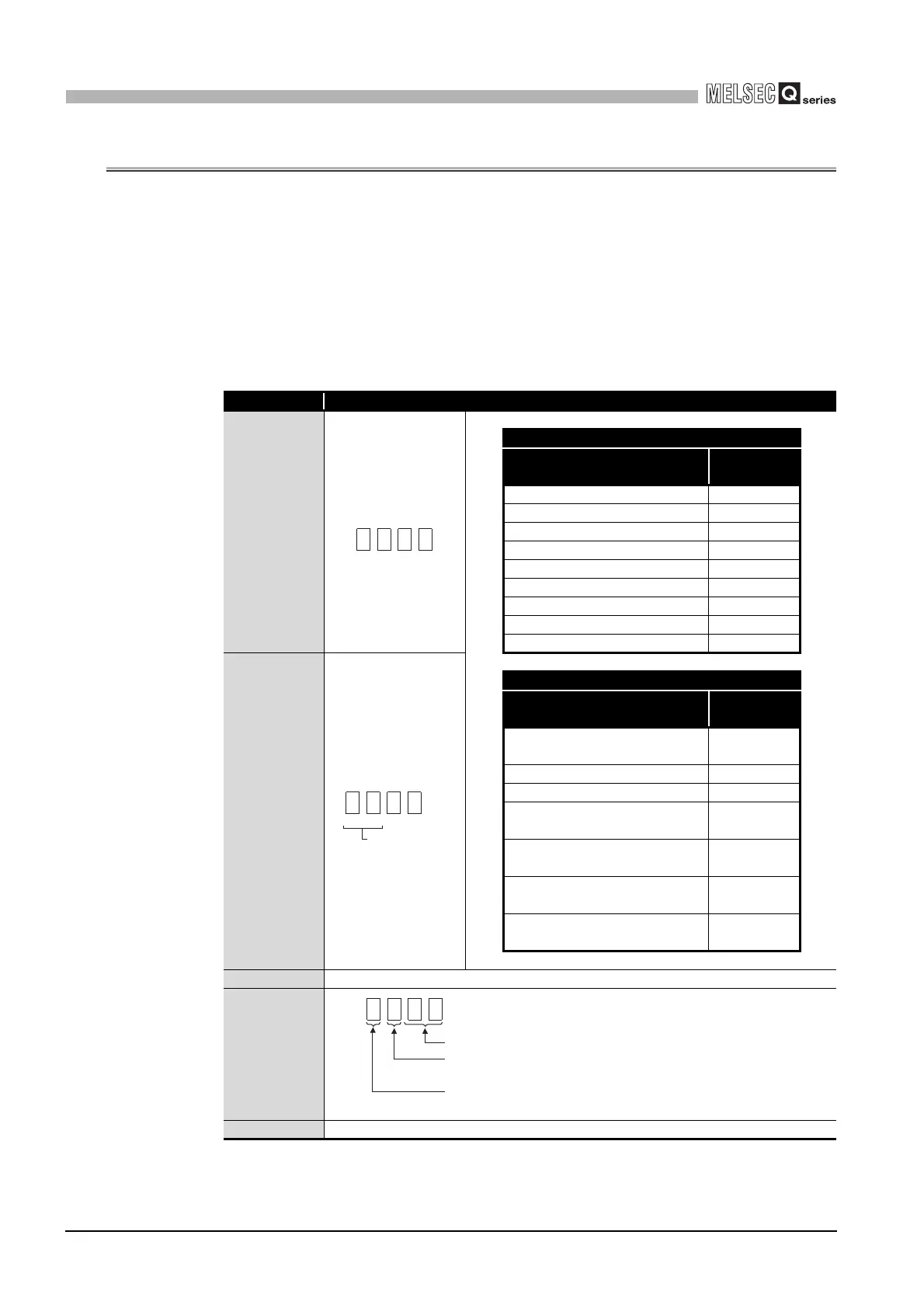
(1) Setting item
The intelligent function module switches consist of switches 1 to 5 and are set using
16-bit data. When the intelligent function module switches are not set, the default
value for switches 1 to 5 is 0.
*1 Setting any value within the setting range will provide the same operation.
When the setting range is 1
H to FH, set 1H for example.
Table4.1 Switch setting item
Switch No. Setting item
Switch 1
Q68AD-G
Analog input range
Input range
setting value
4 to 20mA 0
H
0 to 20mA 1H
1 to 5V 2H
0 to 5V 3H
-10 to 10V 4H
0 to 10V 5H
4 to 20mA (Extended mode) AH
1 to 5V (Extended mode) BH
User range setting FH
Switch 2
Q66AD-DG
Analog input range
Input range
setting value
4 to 20mA (For 2-wire transmitter
input)
0
H
4 to 20mA (For current input) 6
H
0 to 20mA (For current input) 7
H
4 to 20mA (Extennded mode)
(For 2-wire transmitter input)
A
H
4 to 20mA (Extended mode)
(For current input)
C
H
User range setting (For current
input)
E
H
User range setting (For 2-wire
transmitter input)
F
H
Switch 3 Empty
Switch 4
Switch 5 0H : Fixed
CH4 CH3
Input range setting
(CH1 to CH4)
CH2 CH1
H
CH8 CH7 CH6 CH5
H
Fixed at 00H
for Q66AD-DG
Input range setting
(CH5 to CH8)
H
00H: Fixed
0
H: Normal resolution mode
1
H to FH (value other than 0H)
*1
: High resolution mode
0
H: Normal mode (A/D conversion processing)
1
H to FH (value other than 0H)
*1
: Offset/gain setting mode
 Loading...


