6 - 21
6.4 For Use in Normal System Configuration (Q66AD-DG)
6
PROGRAMMING
6.4 For Use in Normal System Configuration (Q66AD-DG)
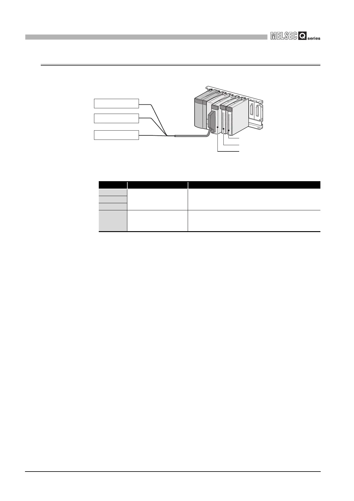
(1) System configuration
(2) Conditions for the intelligent function module switch setting
(3) Program conditions
(a) The following averaging processing specification is used for each channel.
• CH1: Sampling processing
• CH2: Time averaging (50 times)
• CH3: Primary delay filtering (100ms)
(b) CH1 uses the input signal error detection function (Refer to Section 3.2.3.)
• Input signal error detection: 10%
(c) CH2 uses the warning output setting (process alarm) (Refer to Section 3.2.4 (1).)
• Process alarm lower lower limit value: 1000
• Process alarm lower upper limit value: 1500
• Process alarm upper lower limit value: 6000
• Process alarm upper upper limit value: 7000
(d) CH3 uses the warning output setting (rate alarm) (Refer to Section 3.2.4 (2).)
• Rate alarm warning detection period : 50ms
• Rate alarm upper limit value: 0.3%
• Rate alarm upper limit value: 0.1%
(e) In the event of a write error, an error code shall be displayed in BCD format.
The error code shall be reset after removal of the cause.
Input range setting Normal resolution mode/ High resolution mode
CH1 4 to 20mA
(For 2-wire transmitter
input)
High resolution mode
CH2
CH3
CH4
to
CH6
not used -
CH1 external device
CH2 external device
CH3 external device
QY10 (Y20 toY 2F)
QX10 (X10 to X1F)
Q66AD-DG (X/Y0 to X/YF)
 Loading...


