4 - 8
4.4 Wiring
4.4.2 External wiring
4
SETUP AND PROCEDURES BEFORE OPERATION
4.4.2 External wiring
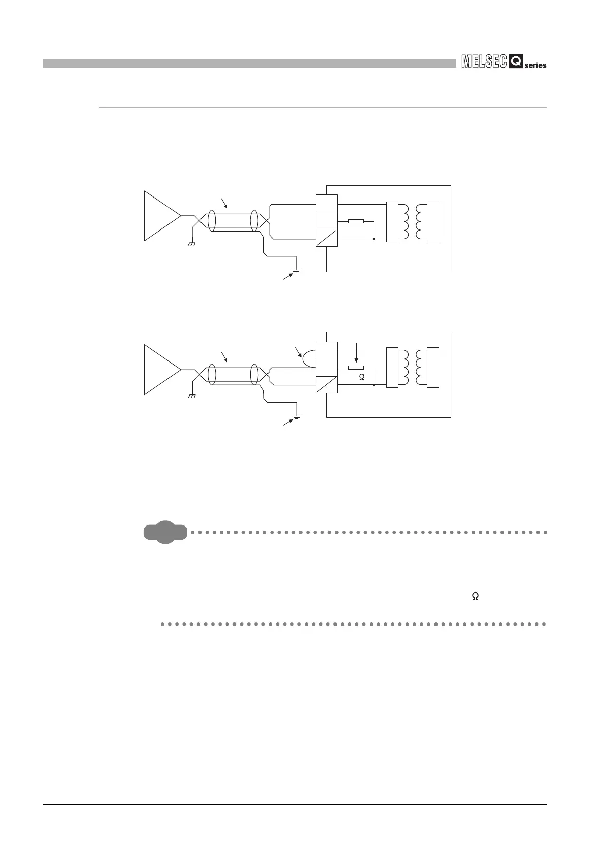
(1) Q68AD-G
(a) For voltage input
(b) For current input
*1: Use a 2-core twisted shielded wire for the power wire.
*2: Shows input resistance.
*3: For current input, be sure to connect (V+) and (I+) terminals.
*4: Connect (V+) terminal to (I+) terminal in the external device connection connector to reduce
resistance of the connection conductor.
*5: Always ground the shield of the wire of each channel.
If the external wiring is disconnected during use of voltage input on the Q68AD-G,
depending on the internal circuit characteristics, a certain time is required until the
digital output reaches a value equivalent to 0V.
To avoid the phenomenon, connect a resistor (approximately 1M ) across (V+)
and (V-) terminals.
V+
I+
V-
I-
*5
Shield
Signal source 0 to ±10V
Modulator
Demodulator
*1
GND
V+
I+
*1
*5
*2
Shield
*3, *4
Signal source 0 to 20mA
V-
I-
Modulator
Demodulator
250
GND
 Loading...


