3 - 67
3.4 Buffer Memory
3.4.16 CH[ ] scaling value storage area (Un\G54 to Un\G61)
3
SPECIFICATIONS
3.4.16 CH
[ ]
scaling value storage area (Un\G54 to Un\G61)
(1) Digital output values after scaling are stored for respective channels.
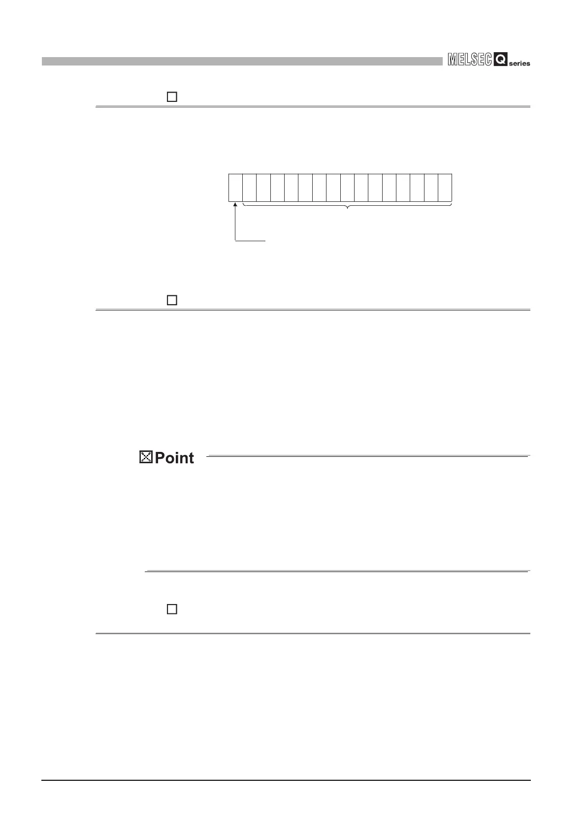
(2) Scaling values are stored as 16-bit signed binaries.
3.4.17 CH
[ ]
scaling upper / lower limit value (Un\G62 to Un\G77)
(1) For each channel, set a scaling range.
(2) To validate the setting, the operating condition setting request (Y9) must be turned
ON/OFF. (Refer to Section 3.3.2.)
(3) The setting range is -32000 to 32000.
(4) Refer to Section 3.2.6 for details of the scaling function.
(1) Setting a value outside the above setting range or a value that does not meet
the inequality "Upper limit > Lower limit" will cause an error. If this occurs, an
error code is stored in Error code (Un\G19) followed by ON of the Error flag
(XF), and the module will operate under the setting before the error.
(2) Since the default setting is 0, change the setting.
(3) When the Scaling enable/disable setting (Un\G53) is set to "Disable", scaling
upper/lower limit values are ignored.
3.4.18 CH
[ ]
conversion starting time setting (for 2-wire transmitter)
(Un\G78 to Un\G83) (Q66AD-DG only)
(1) This area is used to set the "time necessary from when the used 2-wire transmitter
powers on until its output stabilizes" on a channel basis.
This setting is valid only for the channels that use input ranges of "4 to 20mA (2-wire
transmitter): 0
H
" or "User range setting (2-wire transmitter): F
H
", and that are set as
conversion-enabled in the A/D conversion enable/disable setting (Un\G0). It is
ignored in the case of any other setting.
(2) To validate the setting, the operating condition setting request (Y9) must be turned
ON/OFF. (Refer to Section 3.3.2.)
b15
Un\G54 to Un\G61
b14b13b12 b11 b10 b9 b8 b7 b6 b5 b4 b3 b2 b1 b0
Bit data section
Sign bit
1: Negative
0: Positive
 Loading...


