3
SPECIFICATIONS
3.4 Buffer Memory
3.4.5 CH[ ] digital output value (Un\G11 to Un\G18)
3 - 58
1
OVERVIEW
2
SYSTEM
CONFIGURATION
3
SPECIFICATIONS
4
SETUP AND
PROCEDURES
BEFORE OPERATION
5
UTILITY PACKAGE
(GX CONFIGURATOR-
AD)
6
PROGRAMMING
7
ONLINE MODULE
CHANGE
8
TROUBLESHOOTING
(3) Use this area or the A/D conversion competed flag (XE) as an interlock to read out the
digital output value.
3.4.5 CH
[ ]
digital output value (Un\G11 to Un\G18)
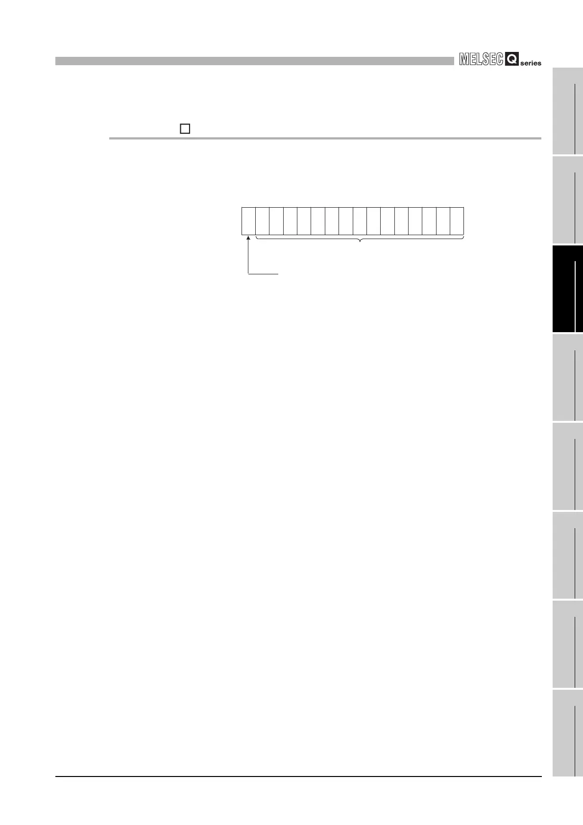
(1) Digital values converted from analog values are stored for respective channels.
(2) Digital values are stored in 16-bit signed binary format.
(3) While the operating condition setting request (Y9) is ON, 0 is stored in this area.
(4) Use the A/D conversion competed flag (XE) or the A/D conversion completed flag
(Un\G10) as an interlock to read out the digital output value.
b15
Un\G11 to Un\G18
b14b13b12 b11 b10 b9 b8 b7 b6 b5 b4 b3 b2 b1 b0
Bit data section
Sign bit
1: Negative
0: Positive
 Loading...


