4
SETUP AND PROCEDURES BEFORE OPERATION
4.4 Wiring
4.4.3 Connector/terminal block converter module
4 - 11
1
OVERVIEW
2
SYSTEM
CONFIGURATION
3
SPECIFICATIONS
4
SETUP AND
PROCEDURES
BEFORE OPERATION
5
UTILITY PACKAGE
(GX CONFIGURATOR-
AD)
6
PROGRAMMING
7
ONLINE MODULE
CHANGE
8
TROUBLESHOOTING
4.4.3 Connector/terminal block converter module
For the following products, please consult your local Mitsubishi Electric sales office or rep-
resentative.
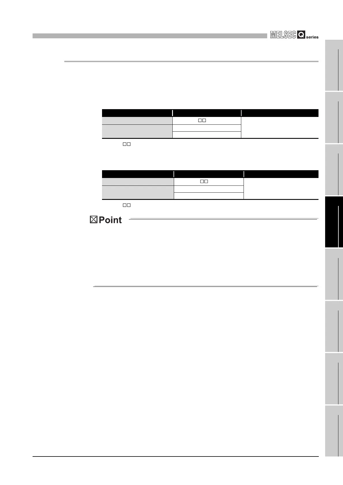
(1) Q68AD-G
*1 shows the cable length (05: 0.5m, 10: 1.0m, 20: 2.0m, 30: 3.0m).
(2) Q66AD-DG
*1 shows the cable length (05: 0.5m, 10: 1.0m, 20: 2.0m, 30: 3.0m).
The offset/gain setting is adjusted in each module (Q68AD-G and Q66AD-DG) at
the factory default setting of the modules.
Therefore an error may occur for the conversion characteristic because of the
influence such as the conductor resistance when a dedicated cable or connector/
terminal block converter module is used.
If a problem occurs by the influence, perform the offset/gain setting by using the
user range setting. (Refer to Section 4.6.)
Product Model Manufacturer
Dedicated cable
FA-CBL Q68ADGN
*1
Mitsubishi Electric Engineering Co.,
Ltd.
Connector/terminal block con-
verter module
FA1-TBS40ADGN
FA-LTB40ADGN
Product Model Manufacturer
Dedicated cable
FA-CBL Q66ADDG
*1
Mitsubishi Electric Engineering
Co., Ltd.
Connector/terminal block con-
verter module
FA1-TBS40ADDG
FA-LTB40ADDG
 Loading...


