3
SPECIFICATIONS
3.3 I/O Signals for the Programmable Controller CPU
3.3.1 List of I/O signals
3 - 34
1
OVERVIEW
2
SYSTEM
CONFIGURATION
3
SPECIFICATIONS
4
SETUP AND
PROCEDURES
BEFORE OPERATION
5
UTILITY PACKAGE
(GX CONFIGURATOR-
AD)
6
PROGRAMMING
7
ONLINE MODULE
CHANGE
8
TROUBLESHOOTING
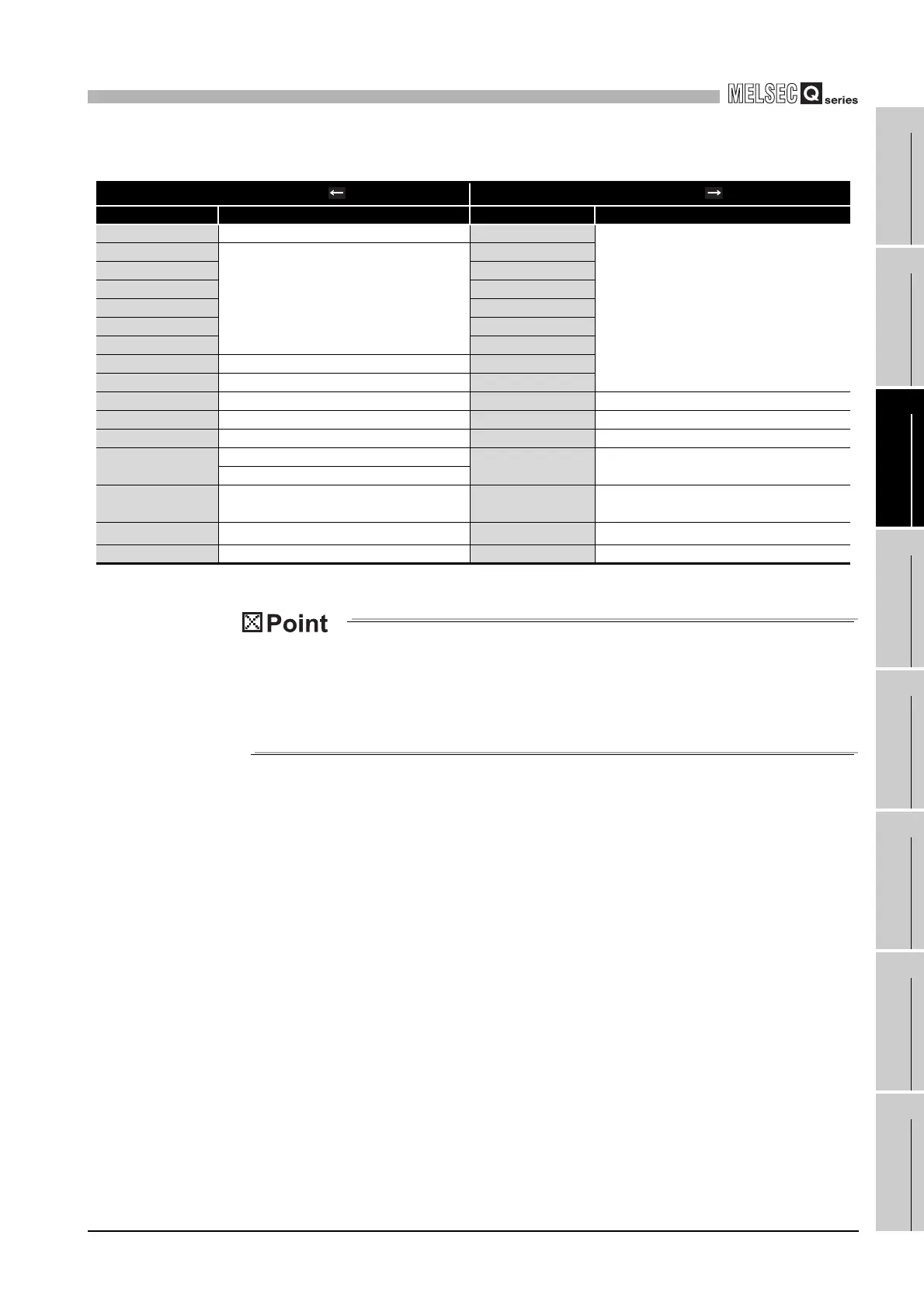
Table3.7 List of I/O signal (Q66AD-DG)
Signal direction CPU Module Q66AD-DG Signal direction CPU Module Q66AD-DG
Device No. (Input) Signal name Device No. (Output) Signal name
X0 Module ready Y0
Use prohibited
*1
X1
Use prohibited
*1
Y1
X2 Y2
X3 Y3
X4 Y4
X5 Y5
X6 Y6
X7 High resolution mode status flag Y7
X8 Warning output signal Y8
X9 Operating condition setting completed flag Y9 Operating condition setting request
XA Offset/gain setting mode flag YA User range writing request
XB Channel change completed flag YB Channel change request
XC
Input signal error detection signal
YC Offset/gain change request
Offset/gain change completed flag
XD
Maximum value/minimum value reset
completed flag
YD
Maximum value/minimum value reset
request
XE A/D conversion completed flag YE
Use prohibited
*1
XF Error flag YF Error clear request
*1 These signals cannot be used by the user since they are for system use
only.
If these are turned ON/OFF by the sequence program, the performance
of the A/D converter module cannot be guaranteed.
 Loading...


