6 - 23
6.4 For Use in Normal System Configuration (Q66AD-DG)
6.4.1 Before creating a program
6
PROGRAMMING
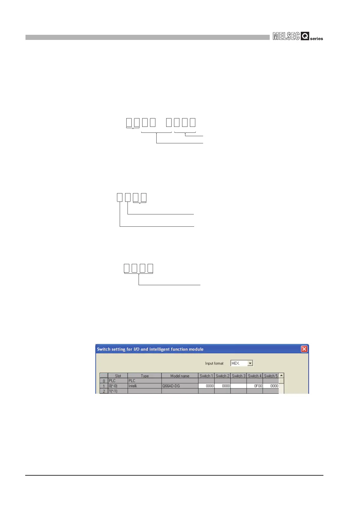
(2) Intelligent function module switch setting
Based on the setting conditions given in Section 6.2 (2), make the intelligent function
module switch settings.
(a) Each switch setting
1) Switch1,Switch2: Input range setting
2) Switch3: Empty (No setting required)
3) Switch4: Mode setting
4) Switch5: Use prohibited (0:fixed)
*1:If any other than 0H is set to Switch 5, an error occurs.
(b) Write the settings in (a) to the Q66AD-DG
On GX Developer’s "Parameter setting" window, select the "I/O assignment" tab,
click "Switch setting", and make settings of Switch 1 to 5 on the window shown
below.
CH4 CH3 CH2 CH1
H
0000
CH6 CH5
H
0000
CH1 to CH3: 0H(4 to 20mA input)
CH4 to CH6: 0H(default)
<Switch 2> <Switch 1>
Fixed at 0
H
Fixed at 0
Setting of normal resolution mode/high resolution mode
All channels: F
H
(High resolution mode)
Setting of normal mode/Offset/gain setting mode
All channels: 0
H
(normal mode)
0F00
<Switch 4>
H
Fixed at 0H
0000
<Switch 5>
 Loading...


