3 - 7
3.1 Performance Specifications
3.1.2 I/O conversion characteristic
3
SPECIFICATIONS
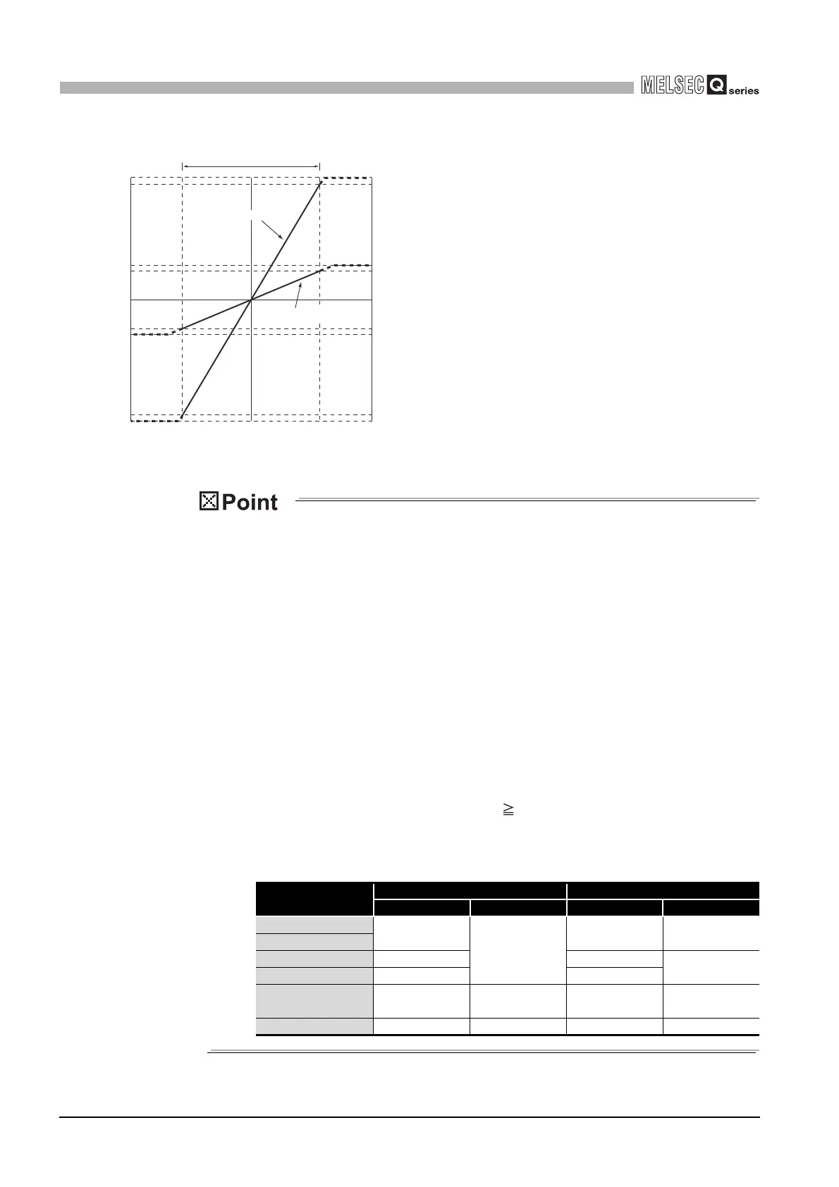
Fig.3.1 Voltage input characteristic of Q68AD-G (2/2)
(1) Set within the analog input range and digital output range for each input
range. If these ranges are exceeded, the maximum resolution and accuracy
may not fall within the performance specifications. (Avoid use shown by the
dotted lines in Fig.3.1.)
(2) Do not input an analog input voltage of -15V or less and 15V or more The
input elements may be damaged.
(3) Set the offset/gain values for the User range setting marked within a range
which satisfies the following conditions.
(a) Offset value, gain value setting range: 10 to 10V
(b) Use one of the following formulas according to the resolution mode to be
set.
1) Normal resolution mode
{ (Gain value) - (Offset value) } > 1.5V
2) High resolution mode
{ (Gain value) - (Offset value) } 4.0V
(4) When an analog value that exceeds the range for the digital output value is
entered, the digital output value will be fixed at the maximum or minimum
value.
Analog input
range setting
Normal resolution mode High resolution mode
Minimum Maximum Minimum Maximum
1 to 5V
-96
4095
-288 12287
0 to 5V
-10 to 10V -4096 -16384
16383
0 to 10V -96 -384
1 to 5V
(Extended mode)
-1096 4595 -3288 13787
User range setting -4096 4095 -12288 12287
Analog input practical range
Digital output value
Analog input voltage (V)
3) -10 to 10V
16383
16000
4095
4000
-4000
-4096
-16000
-16384
0
0
0
10-10
High resolution mode
Normal resolution mode
 Loading...


