3 - 19
3.2 Function List
3.2.3 Input signal error detection function
3
SPECIFICATIONS
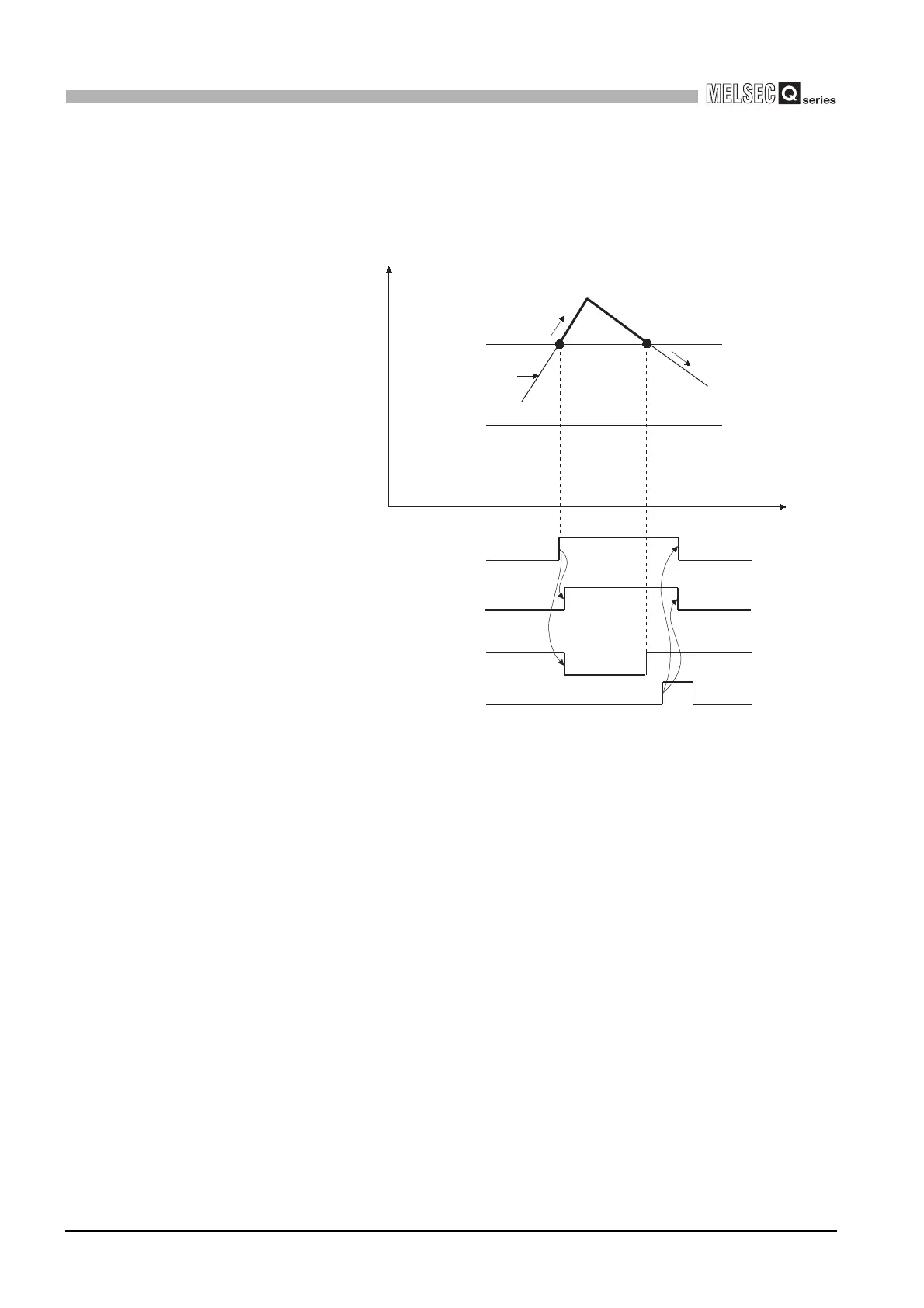
(4) When the analog input value returns to within the setting range, A/D conversion is
resumed independently of whether the input signal error detection flag (Un\G49) and
input signal error detection signal (XC) are reset or not, the A/D conversion completed
flag (Un\G10) of the corresponding channel turns ON again after the first updating.
(The ERR. LED remains flickering.)
(5) This function is executed at every sampling processing.
(6) Perform the following procedure to use this function.
1) Set the input signal error detection setting value for the corresponding channel.
2) Enable the A/D conversion of the corresponding channel.
3) Enable the input signal error detection of the corresponding channel.
4) Turn ON the operating condition setting request (Y9).
Upper limit
value
Lower limit
value
Analog input value
Time
Error detection
CH1 analog
input value
CH1 input signal error detection flag
(Un\G49.b0)
Input signal error detection signal
(XC)
CH1 A/D conversion completed flag
(Un\G10.b0)
Error clear request (YF)
Input value
normal
 Loading...


