3
SPECIFICATIONS
3.3 I/O Signals for the Programmable Controller CPU
3.3.2 Details of I/O signals
3 - 38
1
OVERVIEW
2
SYSTEM
CONFIGURATION
3
SPECIFICATIONS
4
SETUP AND
PROCEDURES
BEFORE OPERATION
5
UTILITY PACKAGE
(GX CONFIGURATOR-
AD)
6
PROGRAMMING
7
ONLINE MODULE
CHANGE
8
TROUBLESHOOTING
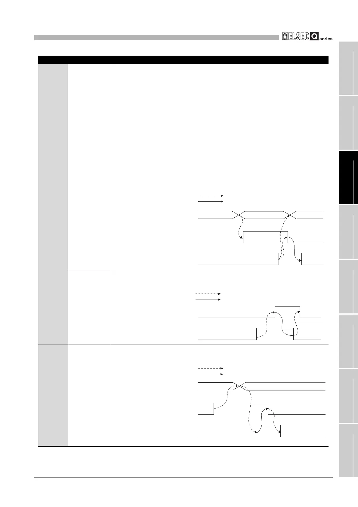
Device No. Signal Name Description
XC
Input signal error
detection signal
(1) This signal turns ON when the analog input value falls outside the setting range set to the Input
signal error detection setting value value/input signal error detection lower limit setting value
(Un\G142 to Un\G149), Input signal error detection upper limit setting value (Un\G150 to
Un\G157) on any of the channels enabled for A/D conversion after the Input signal error detec-
tion is made valid.
(2) When the Input signal error detection signal turns ON
1) The A/D conversion completed flag (Un\G10) of the corresponding channel turns OFF.
2) The digital output value is held as at the time of error detection.
3) The ALM LED flickers.
(3) By bringing the analog input value within the setting range and then turning ON the Error clear
request (YF), the Input signal error detection signal (XC) turns OFF and the ALM LED is
extinguished.
(4) When the analog input value returns to within the setting range, A/D conversion is resumed
independently of whether the Input signal error detection signal (XC) is reset or not, and after
the first updating, the A/D conversion completed flag (Un\G10) of the corresponding channel
turns ON again.
The processing, such as averaging processing or primary delay filter, starts from the first time
after resumption of A/D conversion.
Offset/gain
change
completed flag
*1
(1) This signal is used as an interlock condition to turn ON/OFF the offset/gain change request (YC)
when the offset/gain value is changed.
(2) Refer to Section 4.6 for the offset/gain setting.
XD
Maximum value/
minimum value
reset completed
flag
(1) This signal turns ON when the maximum value/minimum value stored at any of the buffer
memory addresses 30 to 45 (Un\G30 to Un\G45) is reset by turning ON the Maximum value/
minimum value reset request (YD).
0
Input signal error
detection
0
Input signal error detection flag
(Un\G49)
Input signal error detection signal
(XC)
Error clear request (YF)
Performed by the A/D converter module
Performed by the sequence program
Offset/gain change completed flag
(XC)
Offset/gain change request (YC)
Performed by the A/D converter module
Performed by the sequence program
Maximum and minimum values
storage area
(Un\G30 to Un\G45)
Maximum value/minimum value
reset request (YD)
Maximum value/minimum value
reset completed flag (XD)
Performed by the A/D converter module
Performed by the sequence program
 Loading...


