16 Teaching and Setting of Adjustment Variables (
“
1
”
Program)
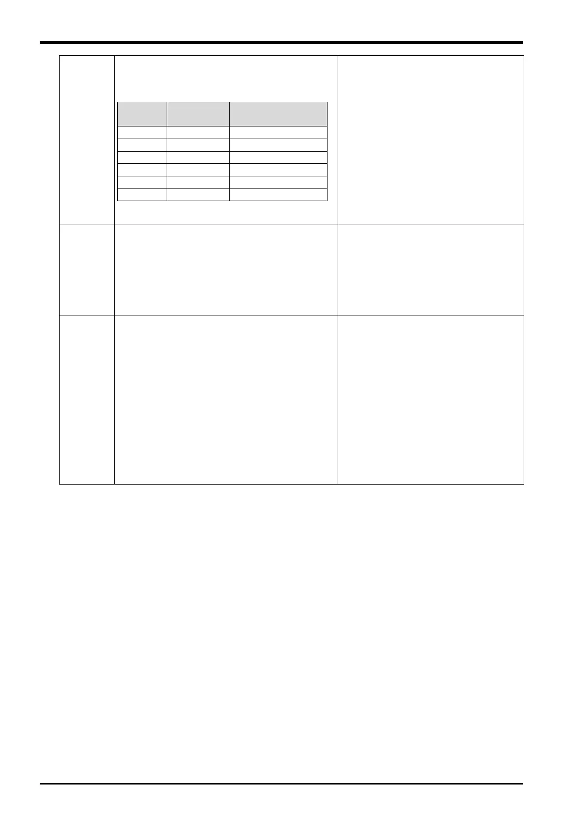
Set the position of the robot and conveyer, and the
direction where the workpiece moves.
X = The following values. (1 to 6)
When a conveyer is placed in front of the
robot and the workpiece moves from the
left to right: (When in view of the robot)
(X, Y, Z, A, B, C) = (+1,+0,+0,+0,+0,+0)
The relationship between PRNG and
PTN is shown in “
Figure 16
3 Diagram
of Relationship between Adjustment
Variables “PRNG” and “PTN” in the
Program
”.
Set range of motion where the robot judges
workpiece to be able to follow.
X = The start distance of the range in which the
robot can follow a workpiece :(mm)
Y = The end distance of the range in which the
robot can follow a workpiece :(mm)
Z = The distance in which follow is canceled
The relationship between PRNG and
PTN is shown in “Figure 16
3 Diagram
of Relationship between Adjustment
Variables “PRNG” and “PTN” in the
Program
”.
The singular point neighborhood can be moved in
RH-3S*HR at the joint operation.
However, when the tracking operation passes
over the singular point neighborhood for straight
line operation, the J1 axis accelerates rapidly and
speed limit (H213x error :x= axis number) is
generated.
Then, the singular point neighborhood is limited to
the tracking by setting this parameter.
X = The Time in which the robot can move over
the workpiece :(ms)
Y = The Maximal speed for J3 axis :(mm/s)
Z = The radius of area made singular point
(+800,+1500,+60,+0,+0,+0)
Refer to “Figure 16−1 Diagram of
Relationship between Adjustment
Variables “PRNG” and “P3HR” in the
Program”
16-80 Setting of adjustment variables in the program

 Loading...


