6
- 29
6.6 Remote Operation
6.6.3 Remote RESET
6
FUNCTIONS
3) WDT error has occurred in standby system in backup mode
If a WDT error has occurred in the standby system, the standby system is not
reset when remote RESET is executed for the control system.
In this case, perform remote RESET in the following path (communication path
where the tracking cable is not relayed).
• Connect the personal computer (GX Developer) directly to the Redundant
CPU of the standby system.
• Execute remote RESET via the standby system module (e.g. remote
RESET using MC protocol).
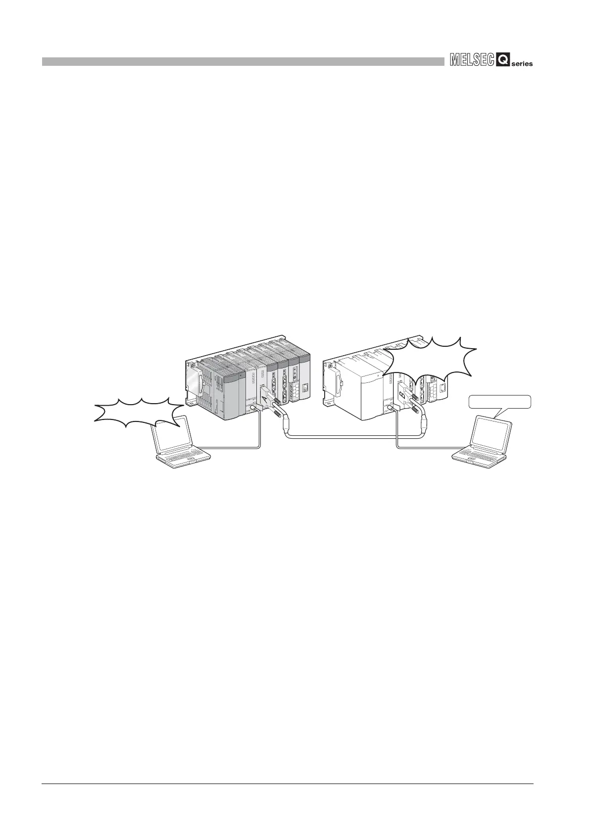
4) When remote operation is performed from the other path in backup
mode
As described in Section 6.6.5 (3), remote operation cannot be performed from
other GX Developer for the CPU module that is executing remote operation.
When remote operation is performed from other path for the control system
and standby system as shown in Diagram 6.20, the standby system may not
be reset if remote RESET is executed for the control system.
When remote operation is performed for the standby system, cancel the
remote operation for the standby system and then execute remote RESET for
the control system.
Diagram 6.20 When remote operation is performed from other path
Standby system
Control system
GX Developer
Remote reset
Reote reset is not
executed!
During remote
GX Developer
 Loading...

