6
FUNCTIONS
6.17 Self-diagnostics Function
6
- 108
1
Overview
2
Performance
Specification
3
Sequence Program
Configuration and
Execution Conditions
4
I/O Nunber Assignment
5
Memories and Files
Handled by CPU Module
6
Functions
7
Communication with
Intelligent Function
Module
8
Parameters
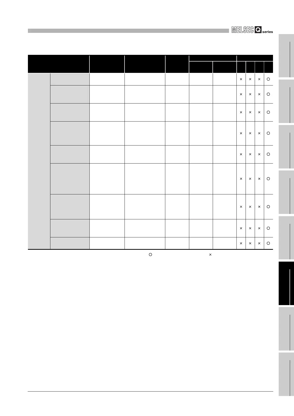
: Self-diagnostics is performed : Self-diagnostics is not performed
* 4 : Since this diagnostics indicates the CPU module status, the error message is not displayed in the
"Current error" field on the PLC diagnostics screen of GX Developer.
This error is displayed in only the error history field.
(Continued on next page)
Table6.29 Self-dianostics list (Continued)
Diagnosics Error message Diagnostics timing
CPU
module
status
LED status CPU module
RUN ERR. 1) 2) 3) 4)
Redundant
system
fault
Tracking data
transmission error
TRK.TRANS.
ERR.
• Always Continue ON ON
Tracking capacity
excess error
TRK.SIZE
ERROR
• When END
instruction is
executed
Continue ON ON
Tracking cable fault,
tracking hardware
failure
TRK.CABLE
ERR.
• When the CPU
module is powered
on/ reset
Stop OFF Flicker
Tracking cable not
connected, failure,
tracking hardware
failure
TRK.
DISCONNECT
• Always Continue ON ON
Tracking initial error
TRK.INIT.
ERROR
• When the CPU
module is powered
on/ reset
Stop OFF Flicker
System switching
(form standby
system to control
system)
occurrence
*4
CONTROL EXE. • Always Continue ON OFF
System switching
(from control system
to standby system)
occurrence
*4
STANDBY • Always Continue ON OFF
System switching
error
CAN’T SWITCH
• When system
switching is
executed
Continue ON ON
Standby system not
started/stop error
STANDBY
SYS.DOWN
• Always Continue ON ON
 Loading...

