3
- 19
3.1 Sequence Program
3.1.3 Interrupt programs
3
SEQUENCE PROGRAM CONFIGURATION AND
EXECUTION CONDITIONS
(5) Save and restoration of index register data and file register No.
When an interrupt program is executed by default of the CPU module, the index
register data and file register block No. are saved and restored at the time of switching
between the scan execution type program/low speed execution type program
Note3.12
and the interrupt program.( Section 9.6.2)Note12
(6) High speed execution setting and overhead time of interrupt program
When "High speed execution" of an interrupt program is selected in the PLC system
settings of the PLC parameter dialog box, the index register data are not saved and
restored at the time of switching from the main routine program to the interrupt
program.
The overhead time of the interrupt program can be reduced.
( CHAPTER 10)
(7) Restrictions on programming
Restrictions on interrupt programming will be explained.
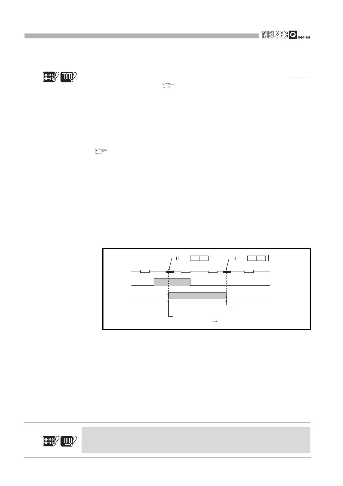
(a) Device turned ON/OFF by instruction such as PLS
When using an instruction such as PLS, by which an execution condition turns ON
from OFF in the next step and it turns the operation device ON, the device
remains ON until the same instruction is executed.
When using an instruction such as PLF, by which an execution condition turns
OFF from ON in the next step and it turns the operation device ON, the device
remains ON until the same instruction is executed.
(b) EI/DI instruction
During execution of an interrupt program, interrupts are disabled (DI) so that any
other interrupt processing will not be executed.
Do not execute the EI/DI instruction during interrupt program execution.
Note12
Diagram 3.16 Device turned ON by PLS in interrupt program
Basic
Note3.12
Redundant
The Basic model QCPU and Redundant CPU cannot be use low speed execution type program.
Basic
Note3.12
Redundant
X0
OFF
ON
M0
OFF
ON
END 0 I0
IRET
END 0 END 0 I0 IRET END 0
PLS M0
X0
PLS M0
X0
Turned OFF when PLS M0
instruction is executed.
Turned ON when PLS M0 instruction is executed on
leading edge (OFF ON) of X0.
 Loading...

