4.3 Tool Connections
The various connections to the system using the cables supplied with the
equipment are specied in “Section 9 - Wiring Details”
4.4 Controller Power Supplies
The control cabinet can be manufactured to accept a wide range of supplies
and sequence of phases. Refer to the serial plate in the controller cabinet
for conrmation of the supply requirements. If the local supply is outside the
specied range, please contact “Section 2 - Global Support” on page 2-1
4.5 Filter Option
In countries where noise across power lines is a concern, Mold-Masters
recommends that you t the model 63AYC10B in-line lter which is supplied
by TC Connectivity.
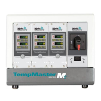
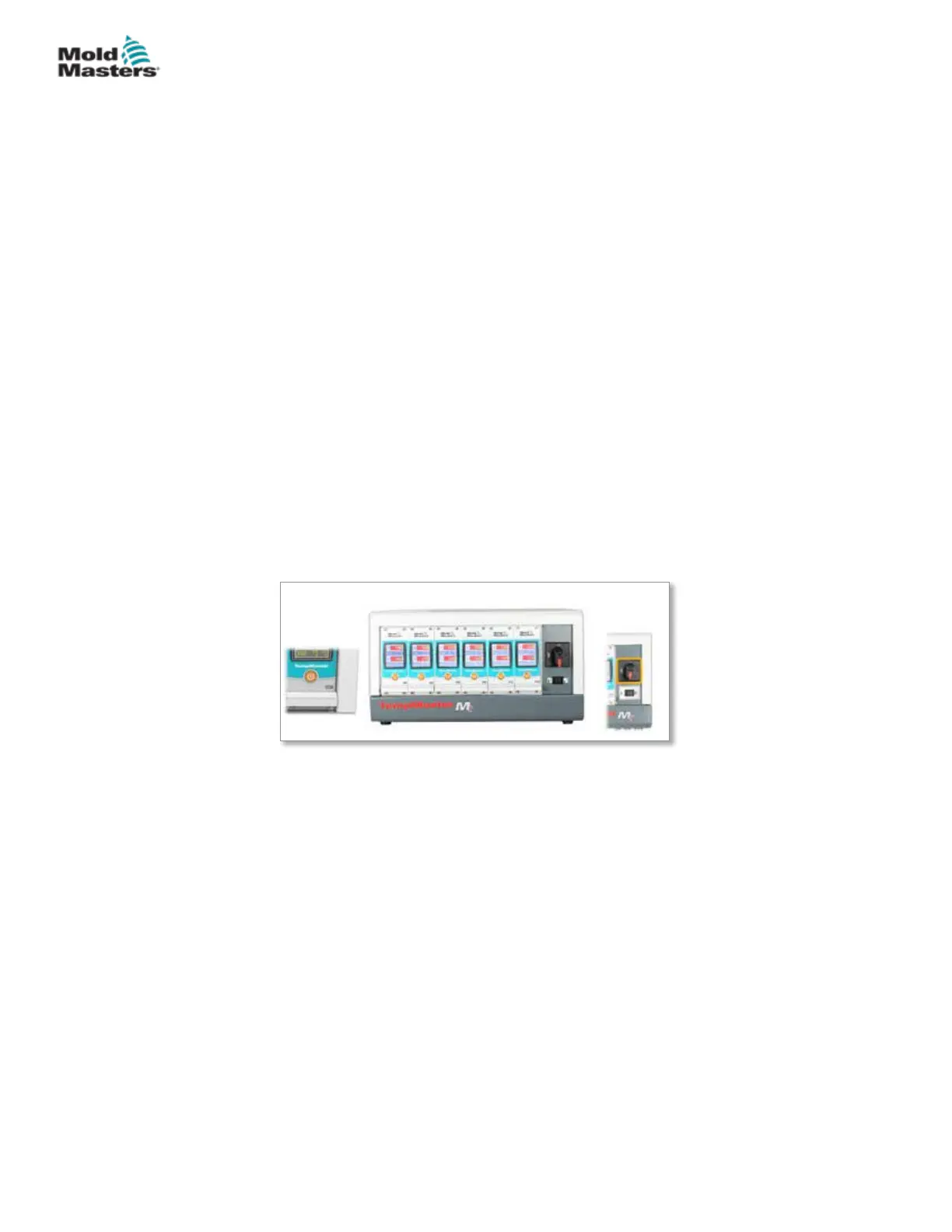
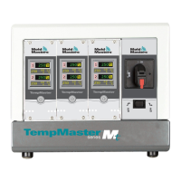
4.6 Switch On and Off
The main power switch is a rotary switch found at the front of the controller. It
is suciently rated to disconnect the total load current during switch on and
switch o.
4.6.1 Switch On
When the controller is switched on, all zones go into “Run” mode and the tool
starts to heat automatically.
4.6.2 Switch Off Individual Modules
Each module has its own power switch. Use the button below the screen to
turn the module o and on.
4.6.3 Switch Off the Whole Controller
When the power to the whole controller is switched o, all zone settings are
memorized. If dierent zones have been set to dierent temperatures to get
optimum performance, then the controller will use those settings the next time
it is switched on.
4-3
© 2020 Mold-Masters (2007) Limited. All Rights Reserved.
OVERVIEW
MT Controller User Manual