7.2.1 Default Settings
These are the settings which would have been applicable when the unit left
the factory and was rst received. They are:
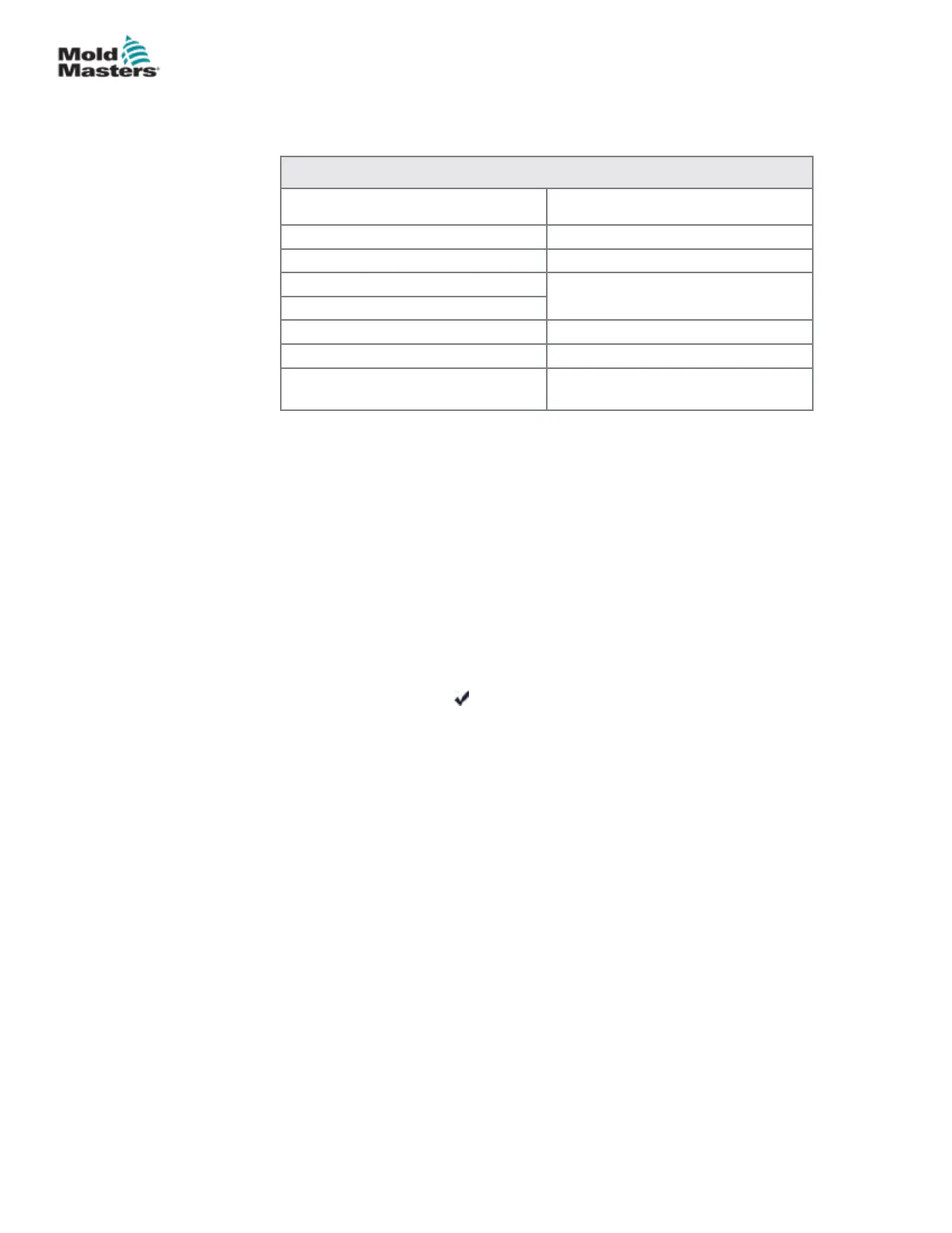
Table 7-1 Factory Settings
Zone Temperature 260ºC or 500ºF
Standby Level 100ºC or 180ºF
Boost Level 75ºC or 135ºF
Over Temperature Range
10ºC or 18ºF
Under Temperature Range
Ramp On
Auto-Man On
Extended Alarms for Manual,
Standby and Boost
O
7.2.2 Calibration Routine
Before starting temperature calibration you need:
• Thermocouple simulator capable of providing accurate set points of
20°C and 400°C.
• Suitable connector plug so that you can connect your simulator to the
appropriate zones without any heater zones being connected. If in
doubt, consult the loom wiring diagram to check for heater and
thermocouple pin connections.
7.2.3 Calibration Sequence
1. Connect the simulator to the normal thermocouple inputs for both zones
on the module being calibrated.
2. Choose [Cal] and [ ] to start the calibration routine.
3. The screen asks for a 20°C source – set your thermocouple simulator to
20°C.
4. The screen timer counts down as it sets the low range setting.
5. The screen asks for 400°C source – set your thermocouple simulator to
400°C.
6. The screen timer counts down as it sets the high range setting.
7. The screen informs you that the calibration has completed.
8. Remove the thermocouple simulator and temporary connector.
7-3
© 2020 Mold-Masters (2007) Limited. All Rights Reserved.
MAINTENANCE
MT Controller User Manual