9.5.6 MT-06-06
One tool connection conguration is used with an MT-06-06 system.
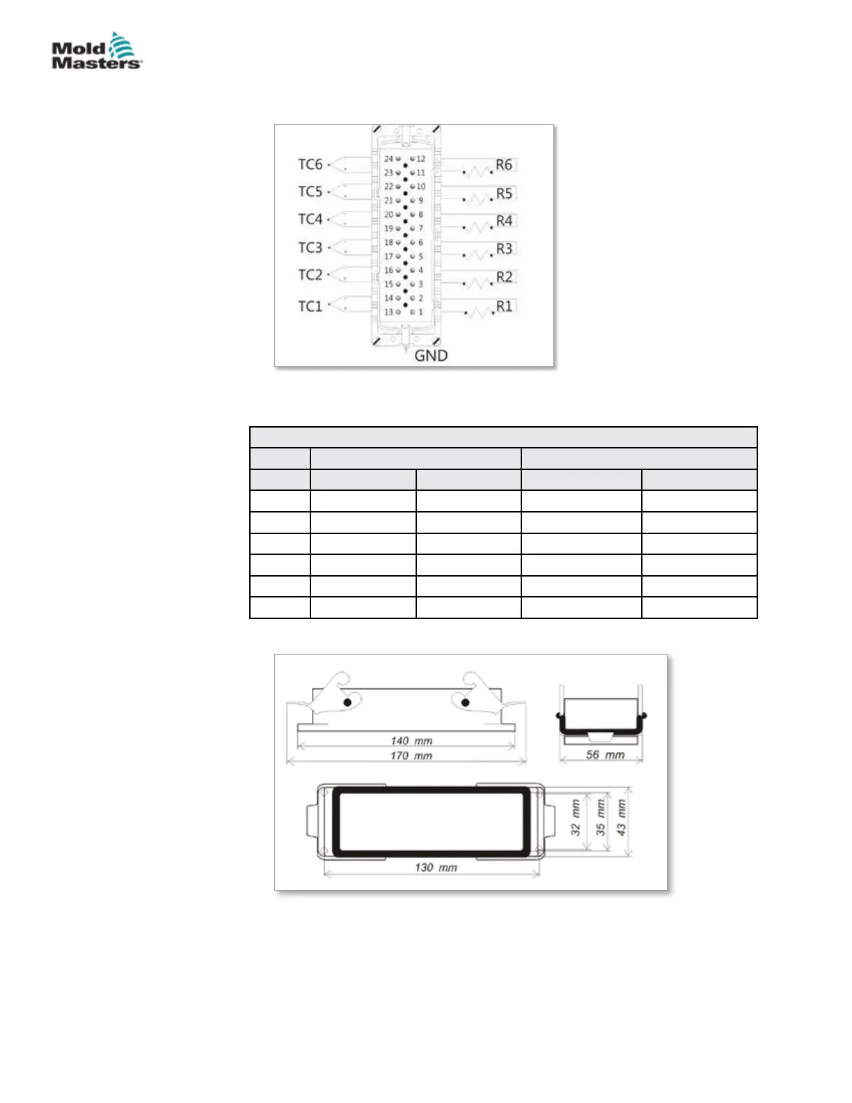
Figure 9-14 Insert for MT-06-06
The pin conguration can be found in Table 9-9:
Table 9-9 MT-06-06 Pin Conguration
Power Thermocouple
Zone Supply Return Thermocouple + Thermocouple -
1 Pin 1 Pin 2 Pin 13 Pin 14
2 Pin 3 Pin 4 Pin 15 Pin 16
3 Pin 5 Pin 6 Pin 17 Pin 18
4 Pin 7 Pin 8 Pin 19 Pin 20
5 Pin 9 Pin 10 Pin 21 Pin 22
6 Pin 11 Pin 12 Pin 23 Pin 24
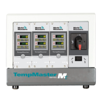
The cut out dimensions are shown in Figure 9-15.
Figure 9-15 MT-06-06 cut out dimensions
Maximum voltage: 230VAC - 16A
9-11
© 2020 Mold-Masters (2007) Limited. All Rights Reserved.
WIRING DETAILS
MT Controller User Manual