9.5 Standard Tool Connections
The following pages show the connections for the MT controller to the tool.
9.5.1 MT-02-02
WARNING
Three dierent congurations are used with an MT-02-02 system,
depending on the geographic location of the controller. It is the
responsibility of the integrator to identify and implement the correct tool
wiring.
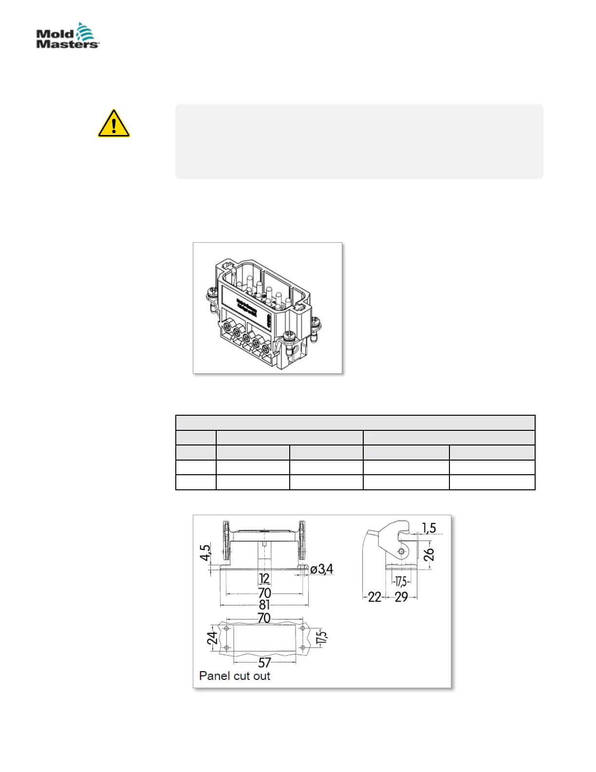
9.5.2 MT-02-02 For UK and Europe
The mold plug for the tool is Harting Han 10 A
®
male insert with Han 10 A
®
single locking level housing. See Figure 9-6.
Figure 9-6 Harting Han 10 A
®
insert for MT-02-02
The pin conguration can be found in Table 9-5:
Table 9-5 MT-02-02 Pin Conguration for UK and Europe
Power Thermocouple
Zone Supply Return Thermocouple + Thermocouple -
1 Pin 3 Pin 4 Pin 1 Pin 2
2 Pin 8 Pin 9 Pin 6 Pin 7
The cut out dimensions are shown in Figure 9-6.
Figure 9-7 Harting Han 10 A
®
cut out dimensions
Maximum voltage: 220VAC - 10A.
9-7
© 2020 Mold-Masters (2007) Limited. All Rights Reserved.
WIRING DETAILS
MT Controller User Manual