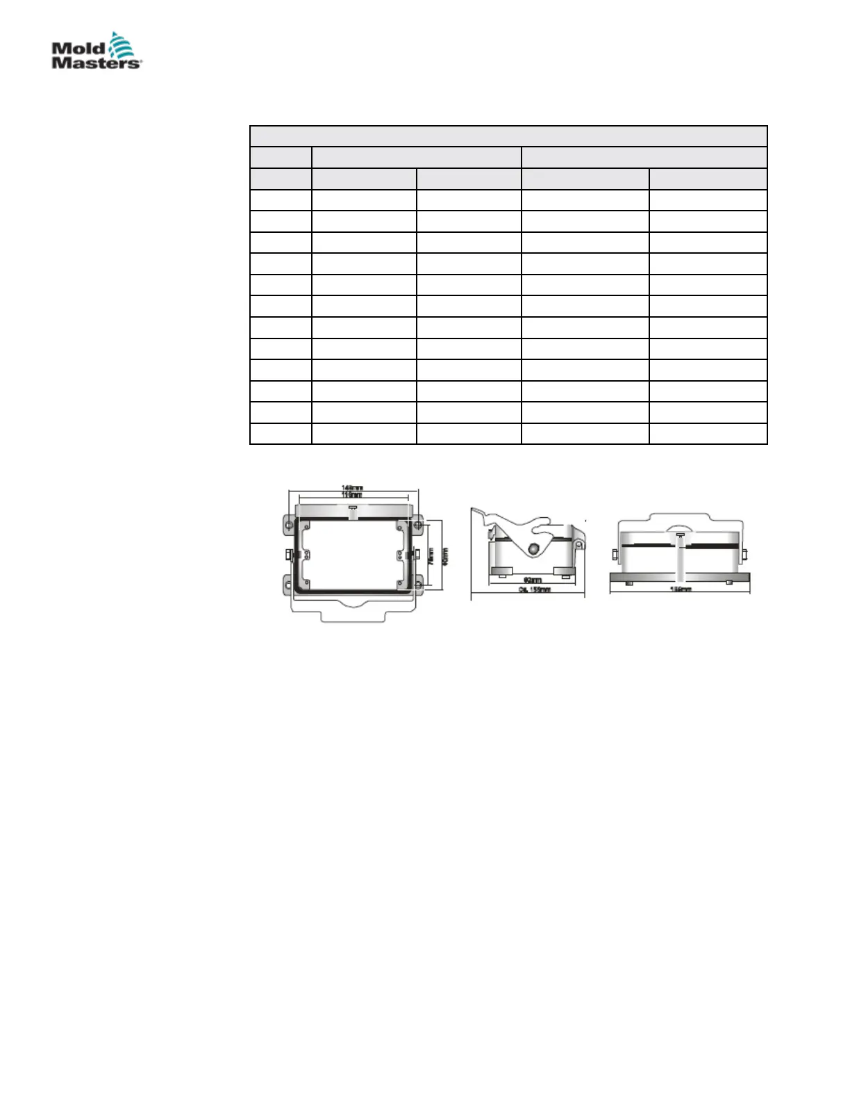
The pin congurations for the female insert can be found in Table 9-12:
Table 9-12 MT-12-12 / MT-18-xx Pin Conguration for North America (Plug 2)
Power (Male) Thermocouple (Female)
Zone Supply Return Thermocouple + Thermocouple -
13 Pin 1 Pin 13 Pin 1 Pin 13
14 Pin 2 Pin 14 Pin 2 Pin 14
15 Pin 3 Pin 15 Pin 3 Pin 15
16 Pin 4 Pin 16 Pin 4 Pin 16
17 Pin 5 Pin 17 Pin 5 Pin 17
18 Pin 6 Pin 18 Pin 6 Pin 18
19 Pin 7 Pin 19 Pin 7 Pin 19
20 Pin 8 Pin 20 Pin 8 Pin 20
21 Pin 9 Pin 21 Pin 9 Pin 21
22 Pin 10 Pin 22 Pin 10 Pin 22
23 Pin 11 Pin 23 Pin 11 Pin 23
24 Pin 12 Pin 24 Pin 12 Pin 24
The cut out dimensions are shown in Figure 9-19.
Figure 9-19 MT-12-12 AND MT-18-xx cut out dimensions - North America
Maximum voltage: 230VAC - 16A
MT-12-12 and MT-18-xx for North America - continued
9-15
© 2020 Mold-Masters (2007) Limited. All Rights Reserved.
WIRING DETAILS
MT Controller User Manual