9.2.4 Set Power Terminal Block To DELTA Conguration
WARNING
Ensure that the controller has been isolated from all power sources before
the wiring is changed.
Cable colors may vary. Always wire up according to the cable markings.
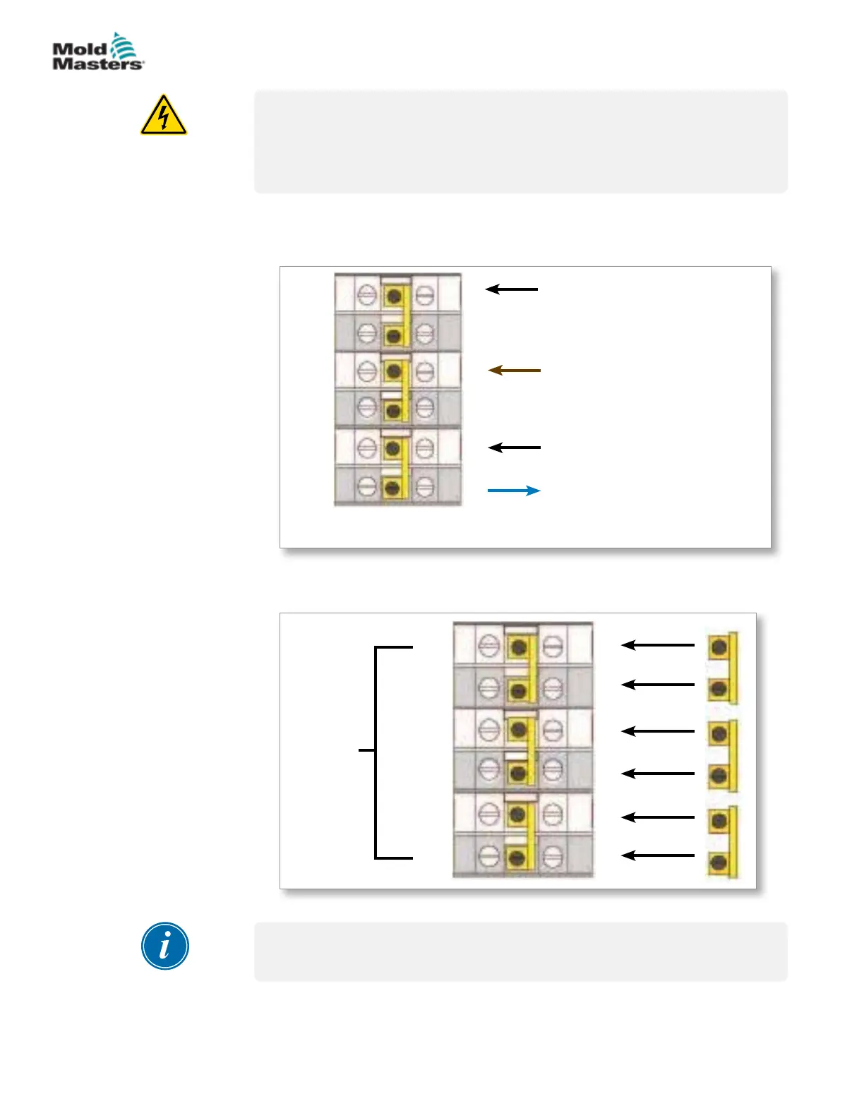
1. Remove the neutral wire of the main power cord from the lower right
terminal as indicated by the blue conductor, and make it safe.
See Figure 9-3.
BLACK
BLACK
BROWN
BLUE - This wire from the
main power cord must be
disconnected and made safe.
R
S
T
MP3
MP2
MP1
Figure 9-3 Remove the neutral wire - position shown by the blue arrow
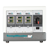
2. Join MP3, MP1 and MP2 with the three 2-way links. Refer to Figure 9-4.
Output to
busbars
R
MP1
S
T
MP3
MP2
Figure 9-4 Install the three 2-way links
IMPORTANT
Do not link MP1, MP3 and MP2 together.
9-5
© 2020 Mold-Masters (2007) Limited. All Rights Reserved.
WIRING DETAILS
MT Controller User Manual