FP0 HardwareSystem Registers
A-6
Matsushita Electric Works (Europe) AG
A.2 Tables of System Registers
C10, C14, C16 and C32 in the table respectively indicate 10-point, 14-point, 16-point
and 32-point type FP0 control units.
The explanations in this chapter often utilize NPST–GR conventions. When using
FPWIN Pro for programming, please note these slight differences:
Hexadecimal values are represented by the prefix 16# and not H.
Decimal values do not require a K prefix.
Moreover in FPWIN Pro, there is an “Additional Information” column for each System
Register that briefly explains its use.
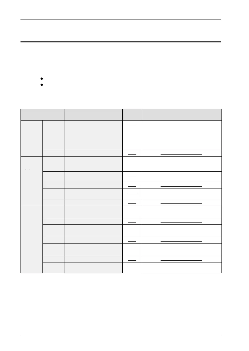
Address Name of system register
Default
value
Set value (parameter)
Allocation
of user
memory
0 Sequence program area
capacity
The set values are fixed and cannot be
changed.
The stored values vary depending on the
model and type.
K3: 3 K words (FP0 C10, C14, C16)
K5: 5 K words (FP0 C32)
1 to 3 Unused
Hold/
Non–
hold
5 Timer and counter division
(setting of leading counter
number)
K100 K0 to K144
For detailed information, see page A-4.
6 to 8 Unused With the FP0, values set with the program-
ming tool become invalid.
9 to 13 Unused
14 Unused With the FP0, values set with the program-
ming tool become invalid.
15 Unused
Action on
error
20 Disable or enable setting for
duplicated output
K0 K0: Disable (will be syntax error)
K1: Enable (will not be syntax error)
21, 22 Unused
23 Operation setting when an I/O
verification error occurs
K0 K0: Stop
K1: Continuation
24, 25 Unused
26 Operation setting when an
operation error occurs
K0 K0: Stop
K1: Continuation
27 to 29 Unused
4 Unused With the FP0, values set with the program-
ming tool become invalid.

 Loading...

