FP0 HardwareSystem Registers
A-12
Matsushita Electric Works (Europe) AG
Address Name of system register
Default
value
Set value (parameter)
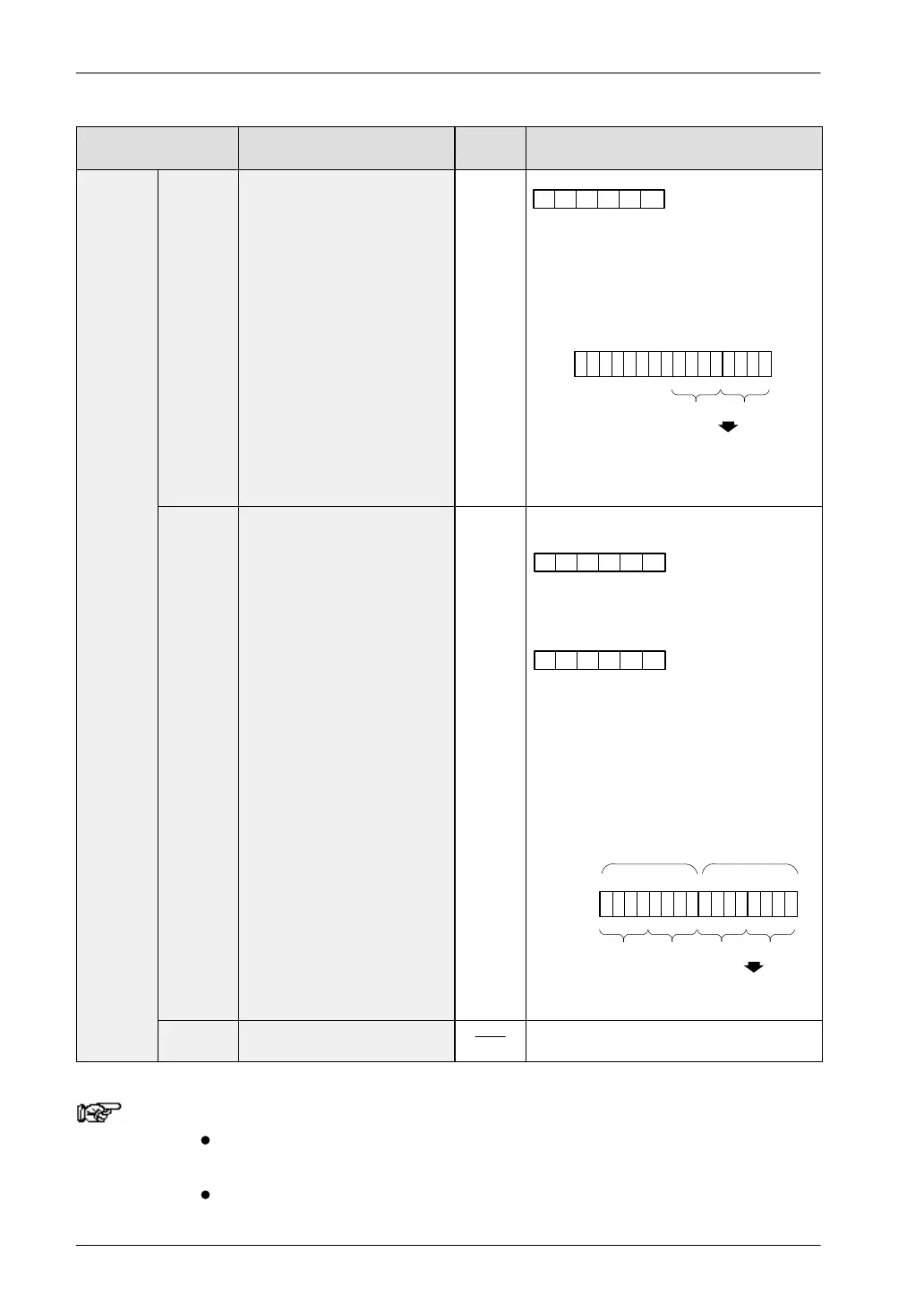
Input
setting
402 Pulse catch input function
settings
H0
0: Standard input
1: Pulse catch input
In FPWIN Pro, select items from the menu.
In FP Programmer II, enter the above set-
tings in hexadecimal.
When X3 and X4 are set to pulse catch input
In the case of FP0, settings X6 and X7 are
invalid.
X5 X4 X3 X2 X1 X0
000000
00011000
15 0
X0
H8H1
402:
Input H18
X1X2X3X4X5
403 Interrupt input settings H0
When setting inputs X0, X1, X2, and X3 as
interrupts, and X0 and X1 are set as interrupt
inputs when going from on to off.
FP programmer II:
Specify the input con-
tacts used as interrupt
inputs in the upper
byte.
Using NPST–GR ver. 4
(0: Standard input/1: Interrupt input)
Specify the effective
interrupt edge in the
lower byte.
(When 0: on/When 1: off)
X5 X4 X3 X2 X1 X0
X5 X4 X3 X2 X1 X0
0011
15 0
X0
HFH0
403:
Input H30F
X1X2X3X4X5
1100
0
0
X0
H3H0
X1X2X3X4X5
11
Specify
edge
Specify
interrupt
In FPWIN Pro, select items from the menu.
404 to
407
Unused With the FP0, values set with the program-
ming tool become invalid.
Notes
With the NPST–GR, “0” or “1” is set for each bit on the screen
in the setting for system register 403.
If system register 400 to 403 are set simultaneously for the
same input relay, the following precedence order is effective:

 Loading...

