FP0 Hardware A.2 Tables of System Registers
A-13Matsushita Electric Works (Europe) AG
[High–speed counter] –> [Pulse catch] –> [Interrupt input].
When the high–speed counter is being used in the incremental
input mode, even if input X0 is specified as an interrupt input
and as pulse catch input, those settings are invalid, and input
X0 functions as counter input for the high–speed counter.
No. 400: H1 <– This setting will be valid.
No. 402: H1
No. 403: H1
Address Name of system register
Default
value
Set value (parameter)
Tool port
setting
410 Unit number setting for tool
port (when connecting
C–NET)
K1 K1 to K32 (Unit No. 1 to 32)
411 Communication format
setting for tool port
Setting item
S Default setting value
S Modem communication:
Disabled
S Data length (character bits):
8 bits
H0
When connecting a modem, set the unit num-
ber to 1 with system resister 410.
Modem communication
0: Disabled
1: Enabled
Data length
(character bits)
0: 8 bits
1: 7 bits
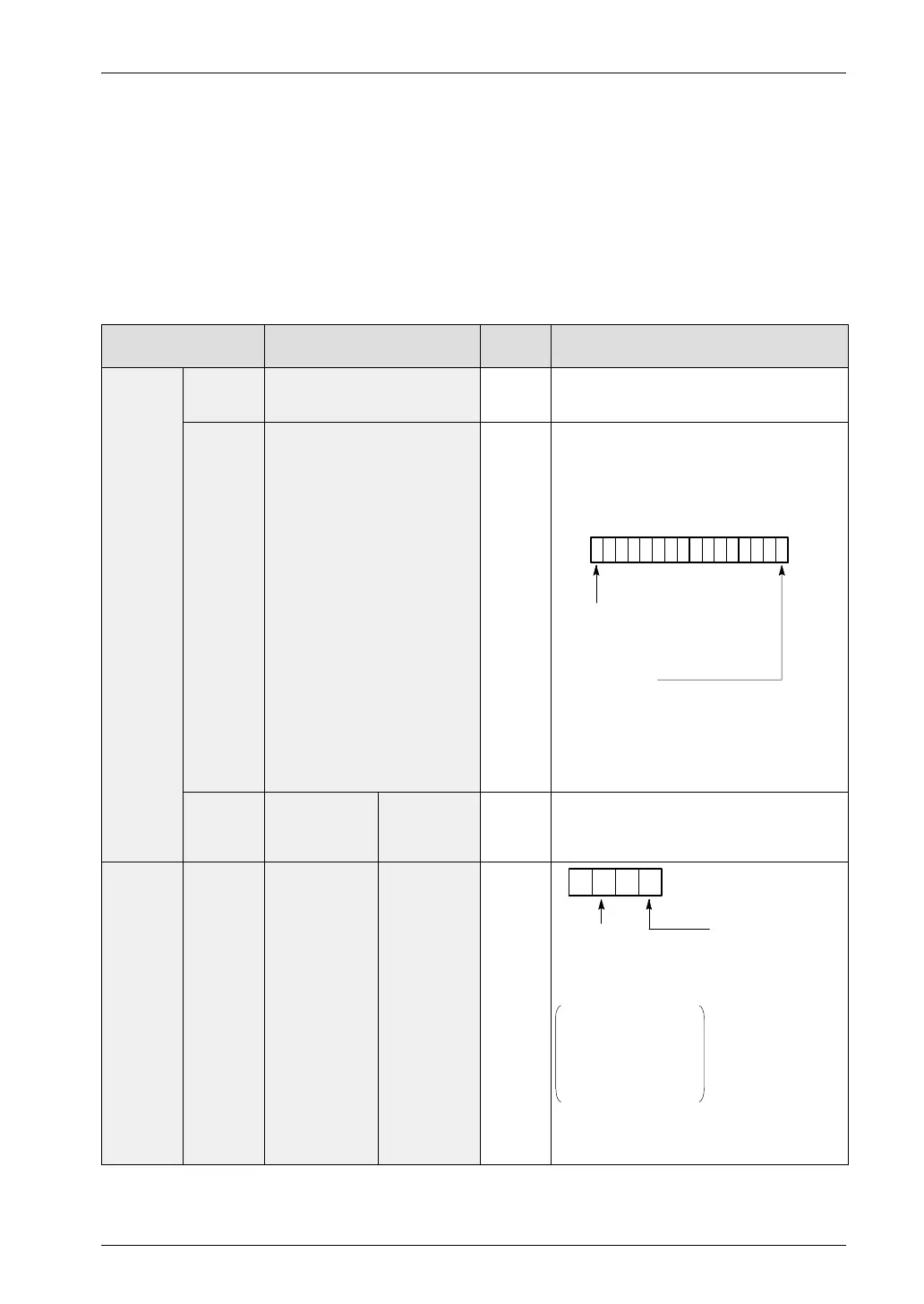
15 06
Using FPWIN Pro or NPST–GR
Select items from the menu.
Using FP programmer II
Specify the setting contents using H
constants.
414 Baud rate
setting for tool
port
Setting by
FPWIN Pro
or NPST–GR
ver. 4
H0 0: 9600 bps
1: 19200 bps
Tool port/
RS232C
port
setting
414 Baud rate
setting for tool
port and
RS232C port
Setting by
FP
programmer
II
H1
RS232C port
H0: 19200 bps
H1: 9600 bps
H2: 4800 bps
H3: 2400 bps
H4: 1200 bps
H5: 600 bps
H6: 300 bps
Tool port
H0: 9600 bps
H1: 19200 bps
If 19,200 bps is set for both the tool port and
RS232C port
–> H100 should be written.
H0 0
If anything other
than H0 or H1 is set
for the tool port baud
rate, the baud rate
will be 9600 bps.

 Loading...

