Setting Up The Networking Feature
ISDN Networking
Networking ◆ 13
Programming
Also refer to the Numbering Plan (page 32) feature for additional
required programming.
➻
10-03-01 : PCB Setup - ISDN Line Mode
Determine the line mode of the ISDN. If Basic Rate Interface (BRI) is chosen, the setting
must be done for each line. The settings must match in all networked systems. The following
entries are acceptable for Networking.
A PRIU PCB will provide up to 24 channels - the BRIU PCB will provide 2 channels. Pro-
gram 10-32-01 can limit the quantity of channels available for PRIU interfaces.
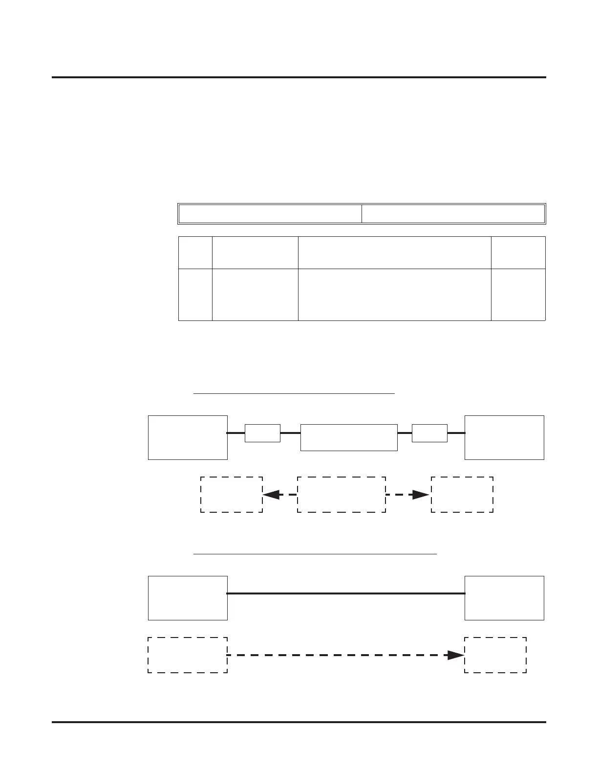
The installation of each mode is shown in the following diagrams.
Mode 3 BRI/PRI Netw
ork Mode (Lease Line)
Mode 4 BRI/PRI Network Mode (Interconnected Line)
ISDN Line Number 01-08
Item
No.
Item Input Data Default
01 ISDN Line Mode 3 = Network Mode (Leased Line)
4 = Network Mode (Interconnected Line)
5 = Interconnection (Interconnected Line,
Fixed Layer 1 Forced NT Mode)
1
Aspire
Mode 3
Master Side
Aspire
Mode 3
Slave Side
NT1 NT1
BRI Leased Line
T<-S
S->T
Slave Slave
Clock Signal
Generator
Aspire
Mode 4
Master Side
Aspire
Mode 4
Slave Side
S->T
Slave
Clock Signal
Generator
 Loading...