Setting Up The Networking Feature
ISDN Networking
14 ◆ Networking
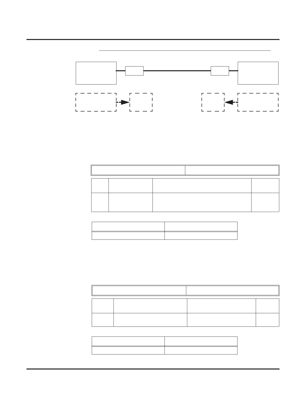
Mode 5 BRI/PRI Interconnection Mode (Interconnected Line, Layer 1=NT)
➻ 10-03-03: PCB Setup - Connection Type
The connection type should be changed if Basic Rate Interface (BRI) is used. Only Point-to-
Point connection (1) is available for system interconnection.
Example:
➻ 10-03-10 : PCB Setup - Master/Slave System
Determine which system will be the master system and which one(s) will be the slave sys-
tem(s). If one system is set as the Master, all the other systems must be set as the Slave. The
choice of Master/Slave is determined by the ISDN clock available at the Aspire. With a direct
connection: Master = S-Point, Slave = T-Point. With a telco connection: Master = T-Point,
Slave = T-Point. See the Appendix (page 237) for further detail.
Example:
ISDN Line Number 01-08
Item
No.
Item Input Data Default
03 Connection Type 0 = Point-to-Multipoint (not available for
Networking)
1 = Point-to-Point
0
System – A System – B
1: Point-to-Point 1: Point-to-Point
ISDN Line Number 01-08
Item
No.
Item Input Data Default
10 Master/Slave System
(Network Mode Only)
0- Slave System
1- Master System
0
System – A System – B
1: Master 2: Slave
Aspire
Mode 5
Slave Side
Aspire
Mode 5
Master Side
GW GW
Ethernet
S<-T
T->S
Slave Slave
Clock Signal
Generator
Clock Signal
Generator
 Loading...