CHAPTER 3 SYSTEM DATA PROGRAMMING
– 98 – NWA-008853-001 Rev.3.0
97ch3001.fm
DESCRIPTION DATA
Assign the necessary functions to each 24DTI/
24CCT cards.
•
(1)
(2)
Y=00 Data Mode
04-15, 20-31: AP No. assigned by CM05
Y=0
0: Based on AT&T Specifications
After entering the data, set the MB switch on
the DTI card to UP, and then to DOWN, for
DTI initialization.
NOTE 1: This command is only applicable for
the 24DTI/24CCT card.
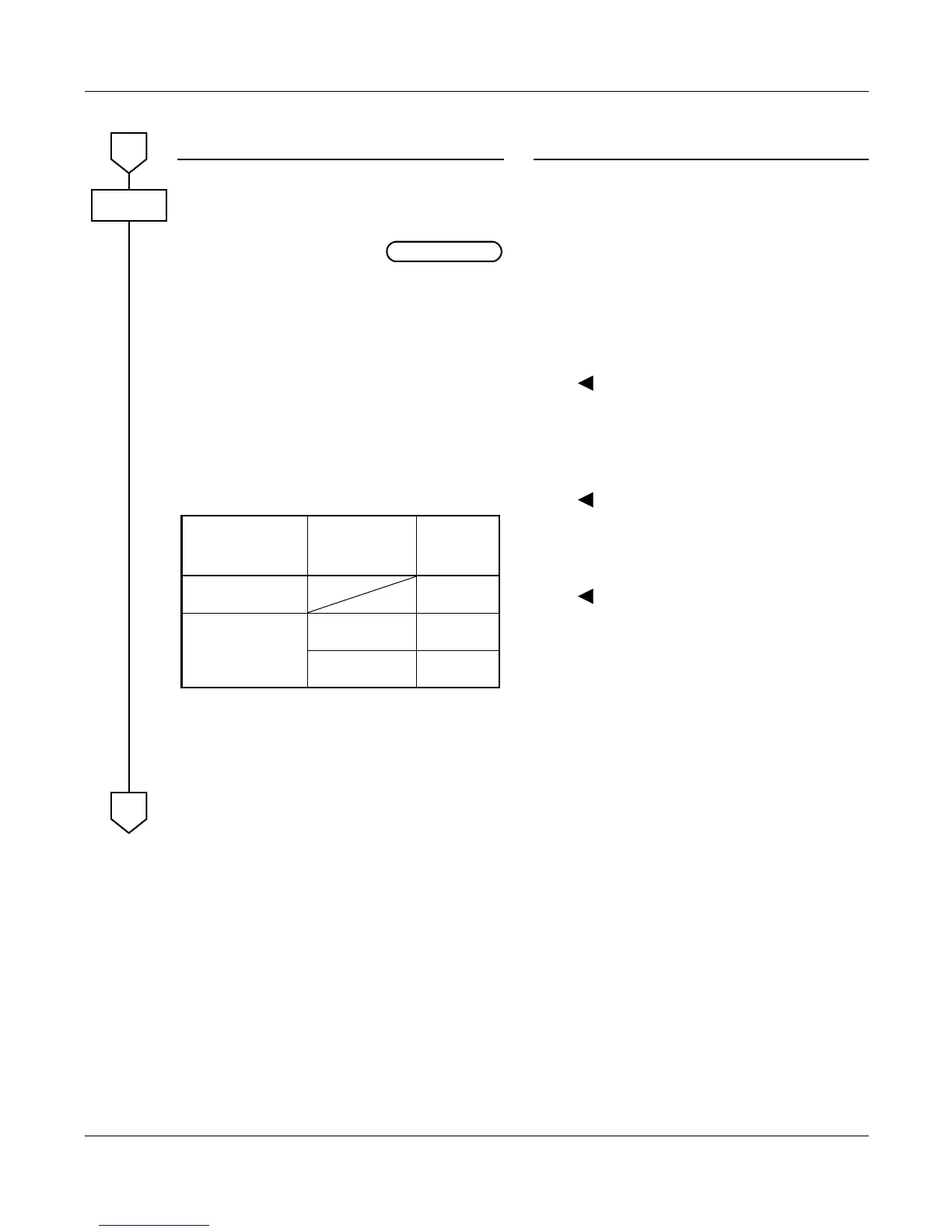
NOTE 2: The following table shows the rela-
tionship between CMAA Y=01 and
Y=02.
[ ] indicates 2nd Data
NOTE 3: If 56K CCIS is used, 24 Multi-
Frame (ESF) must be assigned.
•
(1)
(2)
Y=01 Frame Configuration
04-15, 20-31: AP No. assigned by CM05
Y=0
0 : 12-Multi Frame (D4)
1 : 24-Multi Frame (ESF) NOTE 3
•
(1)
(2)
Y=02 Zero Code Suppression [B7]
04-15, 20-31: AP No. assigned by CM05
Y=0
0 : Available (Non Transparent)
1 : Not available (Transparent)
•
(1)
(2)
Y=03
04-15, 20-31: AP No. assigned by CM05
Y=0
7 : Common Channel Interoffice Signal-
ing
A
CMAA
DTI INITIAL
CMAA Y=01
(FRAME
CONFIGURATION)
CMAA Y=02
(ZERO CODE
SUPPRESSION)
SIGNALING
24-Multi Frame
[1]
B8ZS
12-Multi Frame
[0]
Not available
[1]
Transparent
Available
[0]
B7
B
DIGITAL CCIS PROGRAMMING