DMTA-10055-01EN, Rev. A, February 2015
Gates
123
7. Gates
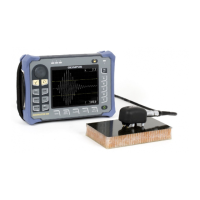
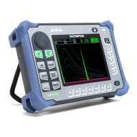
This chapter describes how to use the gates of the EPOCH 650 ultrasonic flaw
detector.
7.1 Measurement Gates 1 and 2
The EPOCH 650 ultrasonic flaw detector has two independent flaw gates. In the A-
scan, a gate is represented by an horizontal line with fixed start and end points. The
length and horizontal position of the line identifies the sound path range, while the
vertical position of the gate line represents a threshold amplitude level for echoes of
interest. In the EPOCH 650, gate 1 appears as a solid red line while gate 2 appears as a
hollow blue line.
Figure 7-1 Gate 1 and gate 2 (with echo-to-echo turned on)
Gate 1 (red)
Gate 2 (blue)
 Loading...

