DMTA-10055-01EN, Rev. A, February 2015
Specifications
305
13.3 Input/Output Specifications
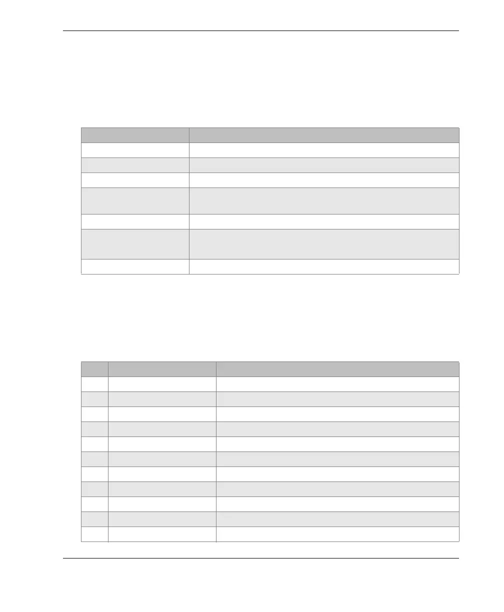
Table 22 on page 305 provides the specifications for the input output signals.
Table 23 on page 305 describes all the connections available on the Digital Out 15-pin
D-sub connector. Table 24 on page 306 describes all the connections available on the
VGA Out 15-pin connector.
Table 22 Input/output specifications
Parameter Va lu e
USB ports 1 USB On-The-Go (OTG)
Video output VGA output standard
RS-232 Yes
Analog outputs 1 analog output, selectable 1 V/10 V full scale, 4 mA max.
(optional)
Alarm outputs 3 alarm outputs, 5 V TTL, 10 mA
Trigger I/O Trigger input, 5V TTL;
Trigger output, 5V TTL, 10mA max
Encoder Inputs 1-axis encoder line (quadrature - Corrosion Module only)
Table 23 EPOCH 650 15-pin digital port output
Pin Signal Description
1 ALARM GATE2 Gate 2 Alarm
2 TRIG OUT Trigger Sync Output
3 RS232 TXD Transmit Data (Serial)
4 RS232 RTC DTR Data Terminal Ready (Serial)
5 RS232 RXD Receive Data (Serial)
6 RS232 CTS DSR Data Set Ready (Serial)
7GNDGround
8 +5V +5 V voltage
9 BSCAN INT X X-Axis Encoder Increment
BSCAN DIR X X-Axis Encoder Direction
GND Ground