DMTA-10055-01EN, Rev. A, February 2015
Software Features and Options
255
characterize ID cracking: the Amplitude Comparison Technique (ACT) and the
Amplitude-Distance Differential Technique (ADDT). The software developed for the
EPOCH 650 aids in performing the ADDT method, which uses the following formula
to determine ID crack size:
where:
d
i
= imperfection size
A
max
= Maximum amplitude returned from defect area (usually 80 %)
T
1
= 6 dB drop point from leading peak of A
max
(distance or time)
T
2
= 6 dB drop point from trailing peak of A
max
(distance or time)
k = A constant calculated from calibration to a reference notch
During an inspection using the ADDT method from the API 5UE practice, a crack that
could possibly be rejected is found and inspected to find its peak amplitude. This
amplitude is then set to 80 % of full screen height (FSH) and designated as Amax. The
transducer is then moved towards the crack until the signal has dropped 6 dB, or to ½
the screen height of A
max
. This position is noted as T
1
. The transducer is then moved
away from the crack until the signal has dropped 6 dB on the other side of A
max
. This
position is noted as T
2
. Using these measurements, along with a k factor constant
calculated during calibration, the crack size d
i
is calculated and recorded.
For further details regarding this calculation, along with the calculation of the “k
factor” constant, refer to API’s Recommended Practice 5UE specification.
The API 5UE software option can greatly simplify the number of operations needed to
perform the ADDT test, and to greatly reduce your overall inspection time. This is
accomplished using the Peak Memory function to draw a peak envelope of the crack
signal and quickly capture the A
max
, T
1
, and T
2
points using a single key press. Using
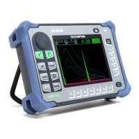
this collected data from the peak envelope, the EPOCH 650 performs the necessary
calculation using the formula above and displays the crack height in the upper right
corner of the screen (see Figure 11-21 on page 256). You can then save all relevant
values of the inspected crack to the data logger for reporting purposes or transfer the
values to a PC using GageView Pro.
 Loading...

