67
Specifications Section 2-2
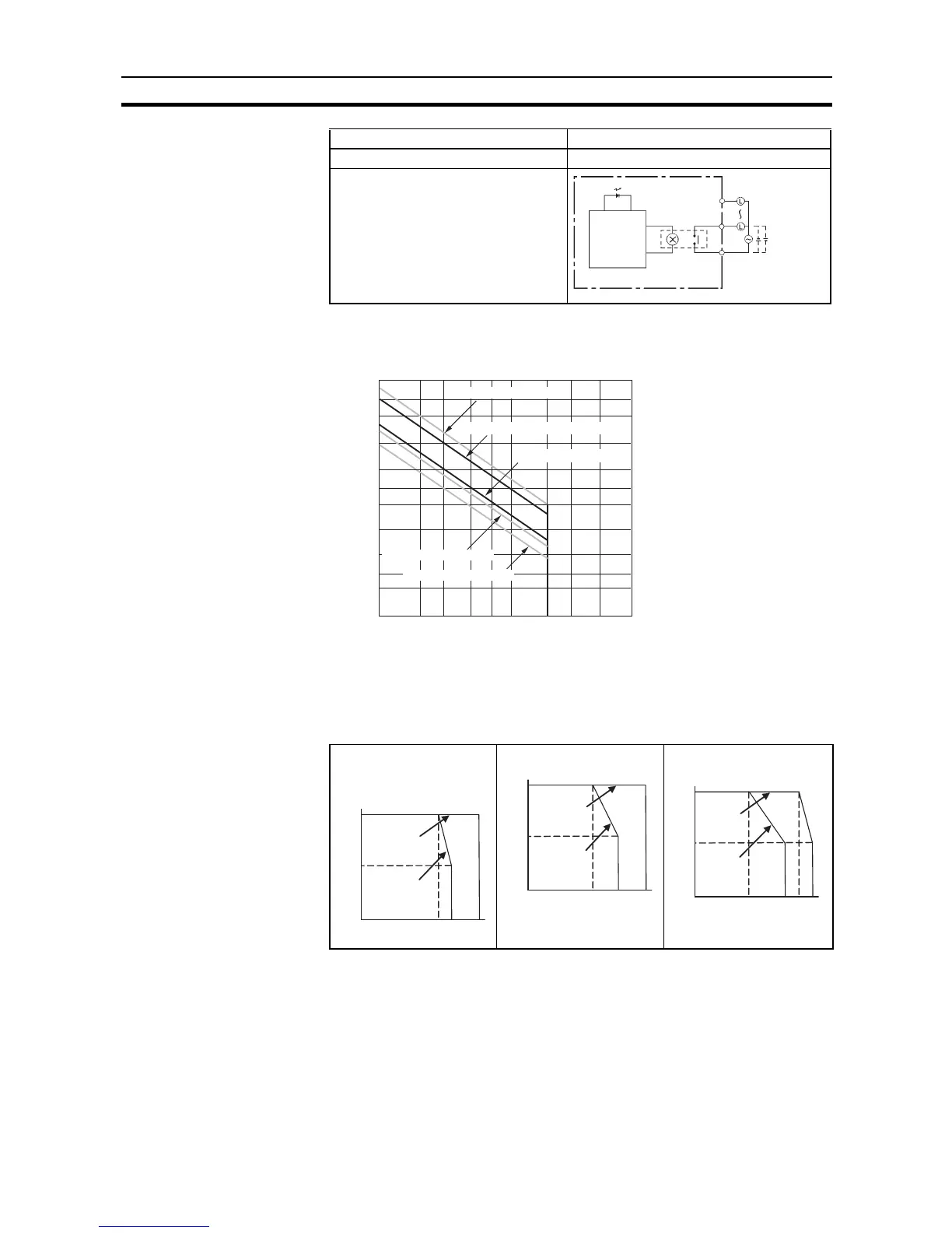
Note (1) Under the worst conditions, the service life of output contacts is as shown
above. The service life of relays is as shown in the following diagram as
a guideline.
(2) There are restrictions imposed by the ambient temperature.
CPU Units with Relay Outputs (CP1L-@@@DR-D)
Relay Output Load Current Derating Curves for CPU Units and Expansion
I/O Units
Note The above restrictions, apply to the relay output load current from
the CPU Unit even if Expansion I/O Units are not connected.
OFF delay 15 ms max.
Circuit configuration
Item Specification
COM
OUT
OUT
Output LED
Internal
circuits
Maximum
250 VAC: 2 A
24 VDC: 2 A
CP1L-L14DR-D
CP1L-L20DR-D
CP1L-J14DR-D
CP1L-J20DR-D
CP1L-M30DR-D CP1L-M40DR-D
CP1L-M60DR-D
300
500
200
100
50
30
20
5
3
2
10
0.1 0.2 0.3 0.5 0.7 1 2 3 5 10
Life (× 10
4
)
Contact current (A)
125 VAC resistive load
30 VDC/250 VAC resistive load
30 VDC τ = 7 ms
125 VAC cosφ = 0.4
250 VAC cosφ = 0.4
50%
100%
55°