105
Mounting Section 3-3
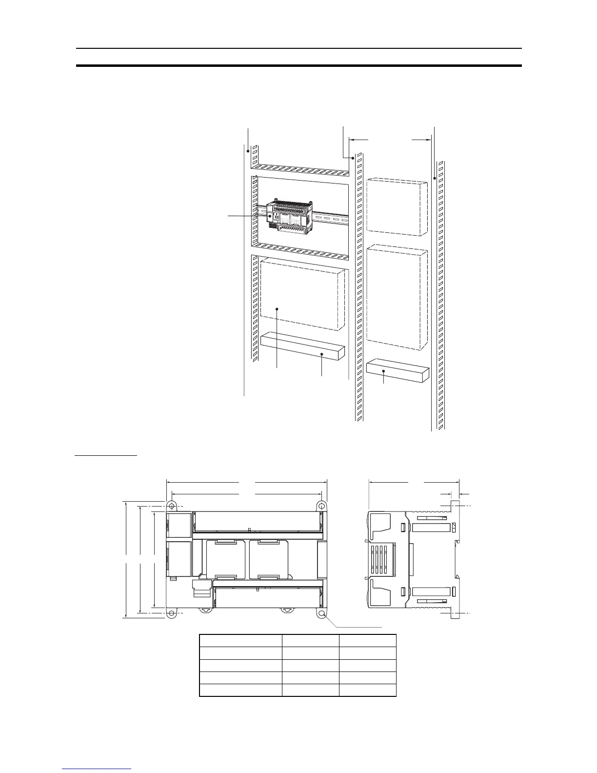
Routing Wiring Ducts Install the wiring ducts at least 20 mm between the tops of the PLC and any
other objects, (e.g., ceiling, wiring ducts, structural supports, devices, etc.) to
provide enough space for air circulation and replacement of Units.
Dimensions
External Dimensions
S
Y
S
M
A
C
C
P
1
H
I
N
B
A
T
T
E
R
Y
A
C
1
0
0
-
2
4
0
V
0
C
H
1
C
H
1
0
1
C
H
1
0
0
C
H
D
C
2
4
V
0
.
3
A
O
U
T
P
U
T
E
X
P
L
1
L
2
/
N
C
O
M
0
1
0
3
0
5
0
7
0
9
1
1
0
1
0
3
0
5
0
7
0
9
1
1
0
0
0
2
0
4
0
6
0
8
1
0
0
0
0
2
0
4
0
6
0
8
1
0
0
0
0
1
0
2
0
3
0
4
0
6
0
0
0
1
0
3
0
4
0
6
C
O
M
C
O
M
C
O
M
C
O
M
0
5
0
7
C
O
M
0
7
C
O
M
0
5
0
7
O
U
T
P
O
W
E
R
E
R
R
/
A
L
M
B
K
U
P
R
U
N
I
N
H
P
R
P
H
L
P
E
R
I
P
H
E
R
A
L
200 mm min.
CP1L
Input duct Output duct Power duc