247
Pulse Outputs Section 5-2
Note This section explains the functions related to pulse outputs only. For details on
the PRV(881) instruction’s high-speed counter or interrupt functions, refer to
6-1 Interrupt Functions
or
5-1 High-speed Counters
.
PULSE WITH VARIABLE
DUTY FACTOR: PWM(891)
PWM(891) is used to output pulses with the specified duty factor.
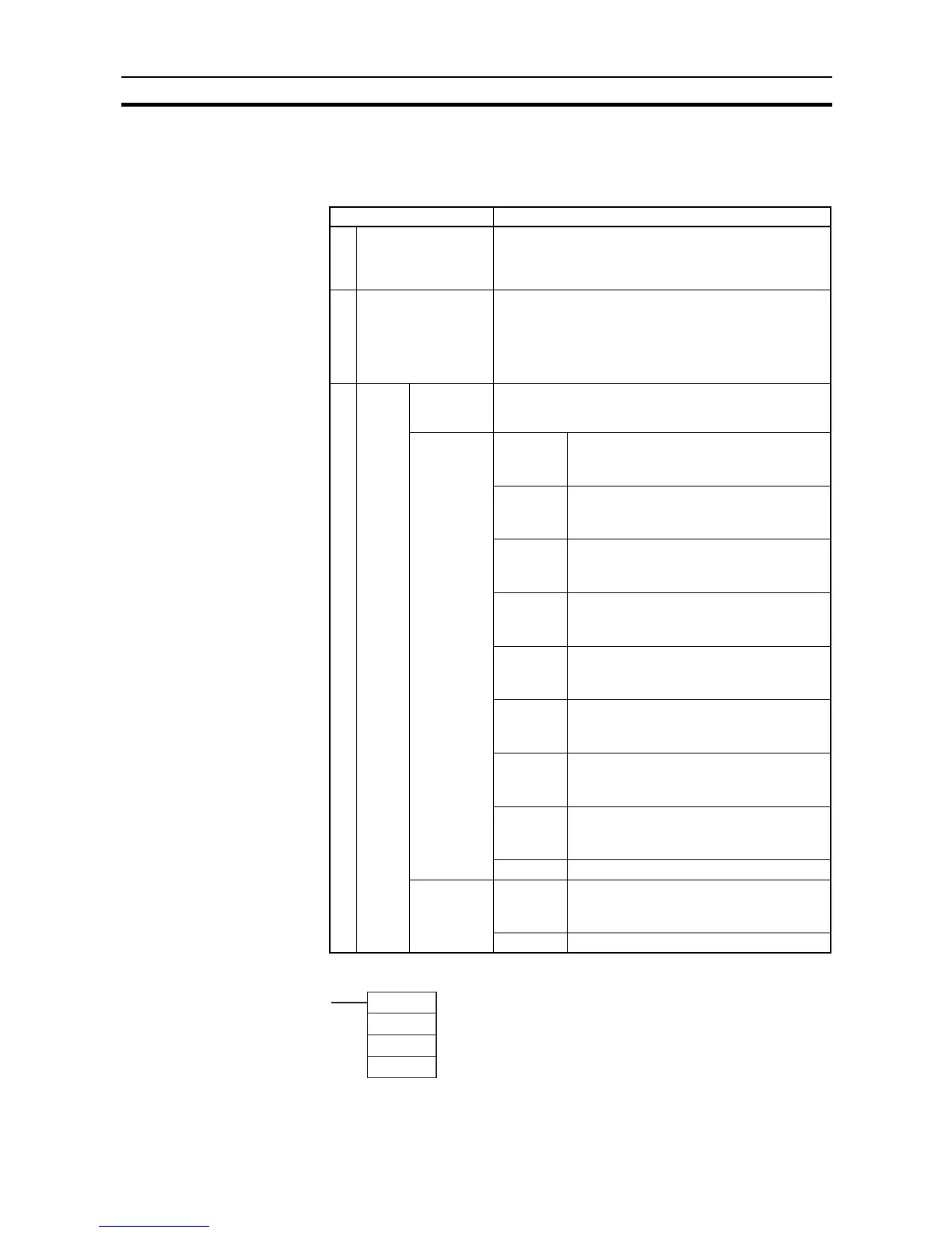
Operand Contents
P Port specifier 0000 hex: Pulse output 0
0001 hex: Pulse output 1
1000 hex: PWM output 0
1001 hex: PWM output 1
C Control data 0000 hex: Read the PV.
0001 hex: Read the status.
0003 hex: Read the pulse output frequency.
0013 hex: Read the frequency for 10-ms sampling.
0023 hex: Read the frequency for 100-ms sampling.
0033 hex: Read the frequency for 1-s sampling.
DFirst
desti-
nation
word
Reading PV
(D and D+1)
After the pulse output PV is read, the 8-digit hexadecimal
data is stored in D and D+1. (D contains the rightmost 4
digits and D+1 contains the leftmost 4 digits.)
Reading
pulse output
status
(D)
Bit 0 Pulse Output Status Flag
0: Constant speed
1: Accelerating/decelerating
Bit 1 PV Underflow/Overflow Flag
0: Normal
1: Error
Bit 2 Pulse Output Amount Set Flag
0: Not set
1: Set
Bit 3 Pulse Output Completed Flag
0: Output not completed
1: Output completed
Bit 4 Pulse Output Flag
0: Stopped
1: Outputting pulses
Bit 5 No-origin Flag
0: Origin established
1: Origin not established
Bit 6 At Origin Flag
0: Not stopped at origin
1: Stopped at origin
Bit 7 Pulse Output Stopped Error Flag
0: No error
1: Pulse output stopped due to error
Bits 8 to 15 Not used.
Reading
PWM output
status (D)
Bit 0 PWM Output Flag
0: Stopped
1: Outputting pulses
Bits 1 to 15 Not used.
PWM
P
F
D
P: Port specifie