324
Inverter Positioning Section 5-3
Serial port 1 is used for communications with the Inverter.
Starting Inverter
Positioning
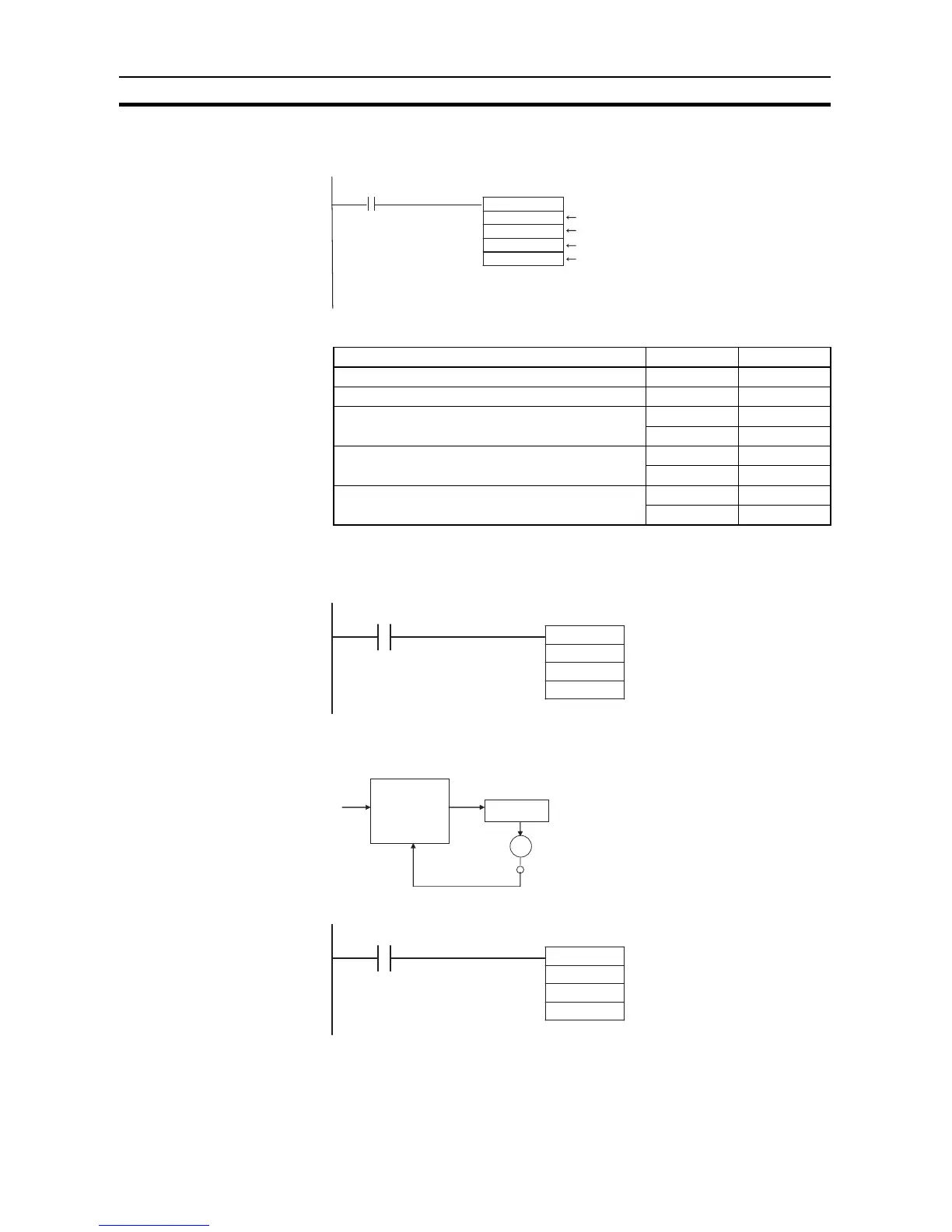
■ PLS2(887) Settings
• High-speed counter 0 (i.e., error counter 0) is used for the feedback pulse
input port.
Stopping Internal Pulse
Output to the Error
Counter
• Internal pulse output is stopped immediately.
• Inverter positioning (i.e., the error counter) will continue to function.
Stopping Inverter
Positioning
• Internal pulse output is stopped immediately.
• The output value will remain at 0 until the error counter is reset.
@PLS2(887)
#0020
#0000
D200
D300
0.05
Start input
Inverter positioning 1
CW, relative pulses
Target frequency, No. of output pulses
Starting frequency
Setting details Address Data
Acceleration rate: 100 Hz/4 ms D200 0064
Deceleration rate: 80 Hz/4 ms D201 0050
Target frequency: 20,000 Hz D202 4E20
D203 0000
Number of output pulses: 600,000 pulses D204 27C0
D205 0009
Starting frequency: 100 Hz D300 0064
D301 0000
@INI
#0020
Port specifier
(Error counter 0: 0020 hex)
#0003 0003 hex: Stop virtual pulse outpu