325
Inverter Positioning Section 5-3
• Pulse outputs will not be accepted until the error counter is reset. (Execut-
ing a pulse output instruction will cause an error.)
Referencing the
Automatically Calculated
Inverter Frequency
Command Value
If the following settings are made in the PLC Setup, the inverter frequency
command value will be calculated automatically and set in A23 in the Auxiliary
Area. These settings are on the Inverter Positioning 0 Tab Page in the PLC
Setup.
• Power Supply Frequency for One Motor Revolution per Second (0.1-Hz
increments)
• Number of Encoder Pulses for One Motor Revolution
• Error Counter Cycle (x 4 ms)
The inverter frequency command value in A23 is accessed. The value is
stored in 0.01-Hz increments.
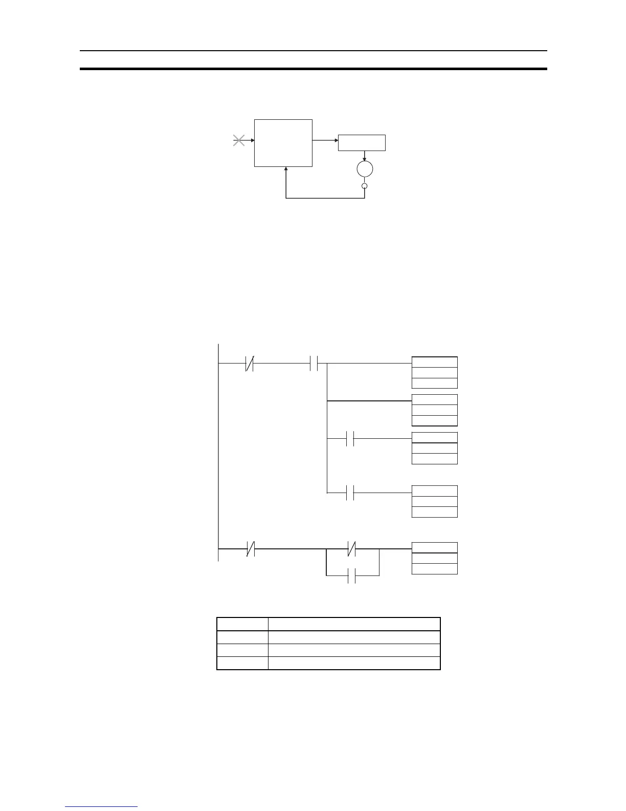
■ Internal Work Addresses
Error counter
Operation
Inverter
Inductive motor
Encoder
Outputs not
accepted
Sets forward
command in
D10.
Sets reverse
command in
D10.
Sets stop
command
in D1.
Sets operation
command
in D1.
Sets frequenc
command
value in D2.
In-position Flag
Operation Command Flag
Forward Command Flag
Reverse Command Flag
Modbus
simple master
function not
active
Operation
Command
Flag
A641.00 A026.00
A26.01
A26.02
A26.00
A26.03
A641.00
MOV
MOV
MOV
MOV
MOV
#0001
D1
A023
D2
#0000
D10
#0001
D10
#0000
D1
Address Usage
D1 Bits 00 to 03: Run/Stop Command
D2 Bits 00 to 15: Frequency Command Value
D10 Bits 00 to 03: Forward/Reverse Command