333
Inverter Positioning Section 5-3
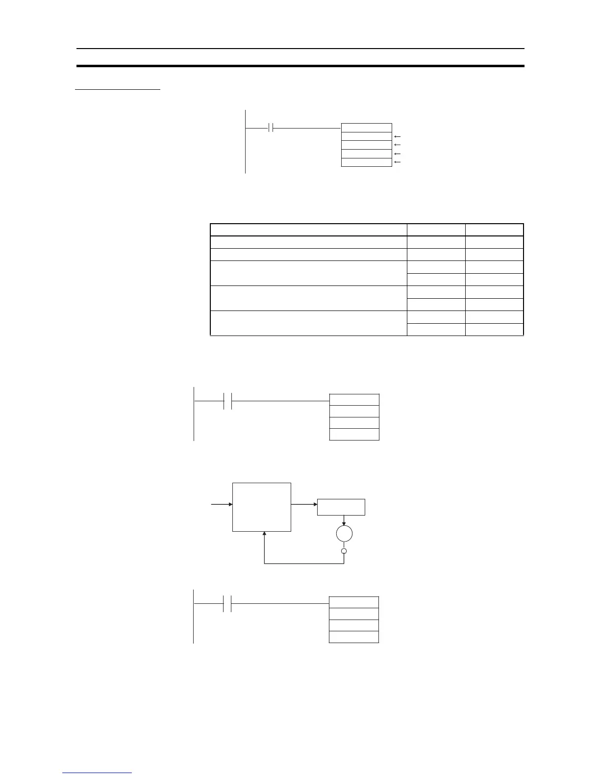
Ladder Program
Starting Inverter
Positioning
Note The pulse output method (CCW/CW or pulse + direction) setting and direction
setting are not used.
■ PLS2(887) Settings
• High-speed counter 0 (i.e., error counter 0) is used for the feedback pulse
input port.
Stopping Internal Pulse
Output to the Error
Counter
• Internal pulse output is stopped immediately.
• Inverter positioning (i.e., the error counter) will continue to function.
Stopping Inverter
Positioning
• Internal pulse output is stopped immediately.
• The output value will remain at 0 until the error counter is reset.
• Pulse outputs will not be accepted until the error counter is reset. (Execut-
ing a pulse output instruction will cause an error.)
PLS2(887)
#0020
#0000
D200
D300
0.05
Start input
Inverter positioning 1
CW, relative pulses
Target frequency, No. of output pulses
Starting frequency
Setting details Address Data
Acceleration rate: 100 Hz/4 ms D200 0064
Deceleration rate: 80 Hz/4 ms D201 0050
Target frequency: 20,000 Hz D202 4E20
D203 0000
Number of output pulses: 600,000 pulses D204 27C0
D205 0009
Starting frequency: 100 Hz D300 0064
D301 0000
0.06
@INI
#0020
#0003
0000
Port specifier (Error counter 0: 0020 hex)
0003 hex: Stop virtual pulse output
0000 (Not used.)
Error counter
Operation
Inverter
Inductive motor
Encoder
Set to 0.
0.07
@INI
#0020
#0004
0000
Port specified (Error counter 0: 0020 hex)
0004 hex: Stop inverter positioning
0000 (Not used.)