601
Auxiliary Area Allocations by Function Appendix C
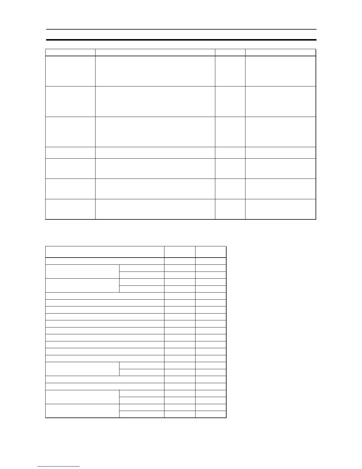
Inverter Positioning
Inverter Positioning 0 and 1
Pulse Output, Output
Stopped Error Flag
ON when an error occurred while outputting pulses in the
pulse output 0 origin search function.
OFF: No error
ON: Stop error occurred.
Read-only • Cleared when power is turned
ON.
• Updated when origin search
starts.
• Updated when a pulse output
stop error occurs.
PWM Output, Output
In-progress Flag
ON when pulses are being output from the PWM output.
OFF: Stopped
ON: Outputting pulses.
Read-only • Cleared when power is turned
ON.
• Cleared when operation starts or
stops.
• Updated when pulse output
starts or stops.
Pulse Output Stop
Error Code
If a Pulse Output Stop Error occurs, the error code is writ-
ten to this word.
Read-only • Cleared when power is turned
ON.
• Updated when origin search
starts.
• Updated when a pulse output
stop error occurs.
Pulse Output Reset Bit The pulse output PV will be cleared when this bit is turned
ON.
Read/Write Cleared when power is turned
ON.
Pulse Output CW Limit
Input Signal Flag
This is the CW limit input signal for the pulse output, which
is used in the origin search. To use this signal, write the
input from the actual sensor as an input condition in the lad-
der program and output the result to this flag.
Read/Write Cleared when power is turned
ON.
Pulse Output CCW
Limit Input Signal Flag
This is the CCW limit input signal for the pulse output,
which is used in the origin search. To use this signal, write
the input from the actual sensor as an input condition in the
ladder program and output the result to this flag.
Read/Write Cleared when power is turned
ON.
Pulse Output Position-
ing Completed Signal
This is the positioning completed input signal used in the
origin search for the pulse output. The input signal from the
servo driver is output to this bit from the ladder program to
enable using the signal.
Read/Write Cleared when power is turned
ON.
Item Inverter
positioning 0
Inverter
positioning 1
Inverter Frequency Command Value A23 A33
Present Value of Unsigned Output
Value
Leftmost 4 digits A21 A31
Rightmost 4 digits A20 A30
Present Value of Signed Output
Value
Leftmost 4 digits A25 A35
Rightmost 4 digits A24 A34
Operation Command Flag A26.00 A36.00
Forward Operation Command Flag A26.01 A36.01
Reverse Operation Command Flag A26.02 A36.02
In-position Flag A26.03 A36.03
Error Counter Error Flag A26.04 A36.04
Error Counter Pulse Output Flag A26.05 A36.05
Error Counter Pulse Output Acceleration/Deceleration Flag A26.06 A36.06
Error Counter Alarm Flag A26.07 A36.07
Inverter Positioning Output Value Sign Flag A26.15 A36.15
Error Counter Present Value, Signed A22 A32
Present Value of Pulse Output to
Inverter, Relative Value
Leftmost 4 digits A29 A39
Rightmost 4 digits A28 A38
Error Counter Reset Bit A562.00 A563.00
Error Counter Disable Bit A562.01 A563.01
Present Value of High-speed
Counter
Leftmost 4 digits A271 A273
Rightmost 4 digits A270 A272
Present Value of Internal Pulse Out-
put
Leftmost 4 digits A271 A279
Rightmost 4 digits A270 A278
Name Description Read/Write Updated