PART 2: CX-Server PLC Tools
CHAPTER 10 – Data Links OMRON
CX-Server PLC Tools_Page 118
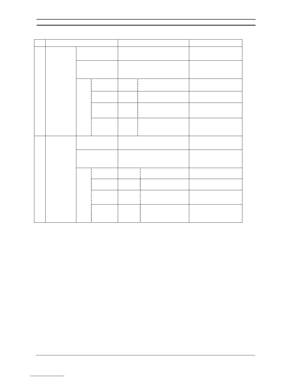
Tag name Description Set value
<start-type>
(Link Area 1 type)
Specify the area type for Link Area 1. Same as for status area type.
<start-ch>
(Link Area 1 start
address)
The beginning word for Link Area 1. Same as for status area start
address.
Node No.
Node
address
The node address for linking
at Link Area 1.
1 to 62
Link start
address
Link word The beginning link word for
Link Area 1.
Set the link start address + link
size for the above link node.
Link size
Size
(Unit:
words)
The link size for Link Area 1. Set any value.
(3) <area1>
<link-
area>
Offset size
Offset The offset size for Link Area
1.
Set any value. If no offset is
required, set 0.
<start-type>
(Link Area 2 type)
The area type for Link Area 2. Same as for status area type.
<start-ch>
(Link Area 2 start
address)
The beginning word for Link Area 2. Same as for status area start
address.
Node No.
Node
address
The node address for
linking at Link Area 2.
1 to 62
Link start
address
Link word The beginning link word for
Link Area 2.
Set the link start address + link
size for the above link node.
Link size
Size (Unit:
words)
The link size for Link Area 2. Set any value.
(4) <area2>
<link-
area>
Offset size
Offset The offset size for Link Area
2.
Set any value. If no offset is
required, set 0.